 Hexastorm
We all love laser scanners, but moving from a wobbly galvanometer to a high-speed rotating prism introduces a whole new nightmare of aberrations. In my previous blog posts, you clearly see that there is an orthogonal error between the scan lines. In addition, there are small timing differences (jitter). So far, no one has been able to handle, let alone quantify this.
My four-facet prism is spinning at 3000 RPM. While the motor controller is keeping the facet timing stable to within 0.2% (where the mean is 5ms per facet), each facet has a slightly different timing signature, which actually allows me to detect which facet is active.
To get usable data, I needed to map the imperfections of every single facet. "Close enough" wasn't going to cut it.
The Setup and The Hack
My optical setup involves a spinning prism directing a laser onto an OV2311 global shutter camera (2MP, with nice square 3.0μm pixels). To see what was happening, I set the camera exposure long (~1000ms) and modulated the laser with a sparse repetitive pattern: a single pulse followed by a long gap [1] * 1 + [0] * 39. This turned the scan lines into distinct strings of dots, freezing the scanner's behavior in time and space. The images are multiple exposures of a facet imposed on top of each other. You can see that the projection is extremely stable. All the smearing or ghost pixels are gone.
The Metrology
Using OpenCV, I grabbed images from all four facets. I detected the dots and fitted ellipses to find their precise sub-pixel centroids. By defining Facet 0 as the "golden" reference, I calculated the relative horizontal and vertical shifts for the other three faces.
The results gave me a perfect digital signature of the prism's physical defects:
| Facet | Timing Shift (Scan μm) | Mechanical Tilt (Orth μm) | Spot Diameter (μm) | Eccentricity |
|---|---|---|---|---|
| 0 (Ref) | 0.0 | 0.0 | 23.023 | 1.307 |
| 1 | 18.171 | 4.177 | 22.35 | 1.464 |
| 2 | 13.45 | 77.707 | 24.801 | 1.577 |
| 3 | 44.907 | 48.889 | 22.826 | 1.363 |
The data is revealing. While the motor timing is stable, the timing synchronization (Scan) varies by over 44 microns between facets. More dramatically, we see massive pyramidal errors (orth-shift). Facets 1, 2, and 3 are all tilted significantly compared to Facet 0, shifting the scan line vertically by nearly 78μm. This is exactly what we were seeing before!
We also see high eccentricity (~1.6). This is expected as I don't use cylinder optics yet but a simple aspherical lens. Still, I am surpised. If the laser spot is 30 microns, we should be able to get much better results; previously, we never really got beyond 75 microns.
Verification
To prove the calibration model works, I did a lot. I repeated the measurements. I switched facets to see if the algorithm is stable. I moved the camera around the laser line to see if the result is consistent. This all proved to be the case.
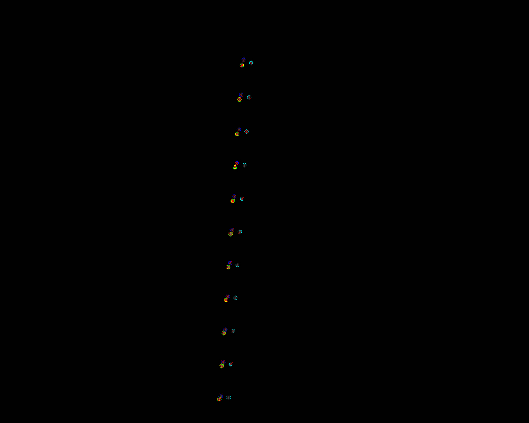
Finally, I generated a composite verification image by stacking the raw captures from all four facets ( a single image is seen all the way on the end).
- Hollow colored circles (cyan, green, red, yellow) are the detected centroids of the actual laser spots.
- Small red 'x' marks are where my calibration model predicts those spots should be after applying the calculated X and Y shifts.
As you can see, the red crosses land dead-center in the detected circles. With this calibration table, I can finally close the loop and feed these precise offsets into the slicer. As a final remark, LLMs are really accelerating the technology innovation here. I really think I am 3 to 4 times faster. Also some problems like, my pi's wifi is not working. Are fixed almost immediately, as the LLM states switch of your power management. This speeds up development 10-fold. As I would previously simply accept and not debug it.

Discussions
Become a Hackaday.io Member
Create an account to leave a comment. Already have an account? Log In.
It's exciting to see the idea of calibrating per facet finally come to pass. I'm very optimistic about the results.
Are you sure? yes | no