-
Hackaday Prize 2020
08/06/2020 at 13:40 • 0 commentsAlthough, I do not plan to participate in the Hackaday Prize 2020. It is inspiring to look for sustainable applications of laser technology.
In 2019, the United Nations set up a campaign for sustainable fashion. Most of the clothes are manufactured in Asia. This process requires a lot of water and produces toxic waste.
Luckily, Dr. Laura Morgan, looked for ways to dye textile with lasers, see her extensive PhD thesis.![]()
She showed that lasers can be used to dye textiles. Results can be seen in the image below.
![]() The laser allows one to locally tune the diffusion of colorant into the textile.
The laser allows one to locally tune the diffusion of colorant into the textile.
She points out multiple benefits for the environment. Production can be done locally,
waste can be reduced and new colors can be added to existing products allowing reuse.In her laser experiments, Dr. Morgan uses 2 Joules per square centimeter. Results are improved with multiple passes, e.g. 15 passes. A carbon dioxide laser is used in her experiments.
She also shows other applications; fading linen, increasing the absorption of wool and applying 3D texture via heat distortion.I think textile coloring could be a nice angle for the Hexastorm. If I have the time, I will do some experiments with a 450 nm laser at 10W. This is much safer than a carbon dioxide laser as infrared light is invisible. The process still requires a washing step but the chemicals involved are a lot less dangerous than the chemicals used for PCBs. The application I see is adding patterns to existing products. I think the process is too slow due to insufficient laser power for large scale production.
Which brings me to an update of my current progress.
At the moment, I am mostly busy with creating the FPGA electronics for the scanner.
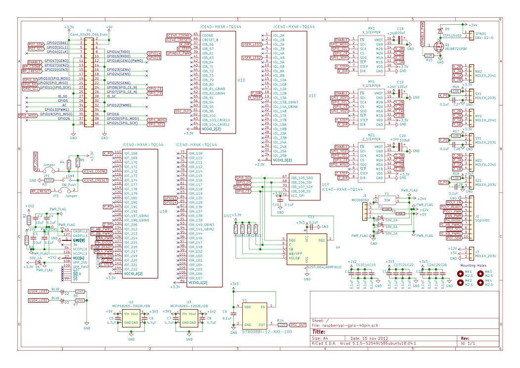
I have made a new board as I made a mistake in the previous board. It turned out that I couldn't use the SPI programming port for sending laser data to the FPGA.
I also wrote new software, this has so far only been tested virtually. -
FPGA Pi Hat blinky
06/11/2020 at 15:38 • 0 commentsManaged to make the LED blink on my custom FPGA board. It was quite a challenge and I am glad I didn't go for a BGA package.
I placed the ICE40 chip on the board with drag soldering. The other components you can hand solder except for the oscillator which requires hot air ( used AYOUE 852) and paste. In the next iteration, I plan to use mainly hot air (it is much faster). Used TS100 as a soldering iron, the Loctice GC10 for paste, flux and some desoldering wire to get the solder on the TQ144 component right. Biggest headache is that I didn't realize I had to send a wake up packet to the flash ram. I tried the python script ice zero prog to flash the memory but it didn' t work; turns out the wake up packet is implemented in icezprog but not in the old python script (OMG!).
Also found out the board has too many caps and resistors, icezero uses less see schema -
FPGA pi hat
05/17/2020 at 13:37 • 2 commentsThe current proof of concept module uses the programmable real time unit of the Beaglebone. This is a device similar to a microprocessor and runs at 200 MHz.
In my next iteration, I plan to use a FPGA. FPGA can be faster and offer more tight control. The current model has a vendor lock to the AM355X ARM core of Texas instruments.
I just finished routing the hat for the Raspberry Pi with uses the ICE40HX4K. This chip comes in a TQ144 package so is easy to solder. The chip is also quite cheap, around 5 euro's. I was able to reuse a lot of the design of the beaglewire and icecore. Information for the laser controller is streamed to the chip via SPI. Maybe in a later stage, I will use the SDIO connector which is faster.Schematic is shown below, full design available here.
![]()
-
Rotor balancer
04/13/2020 at 14:15 • 0 commentsI build a rotor balancer for my prism scanner with an Arduino Nano 33 BLE and an infrared led sensor. I am able to reduce the unbalance of the prism by a factor 10 at a rotor frequency of 90 hertz. Note that for this motor the rotor frequency does not equal the pulse frequency.
The prism seems to have multiple plane unbalance so I was not able to perfectly balance it.
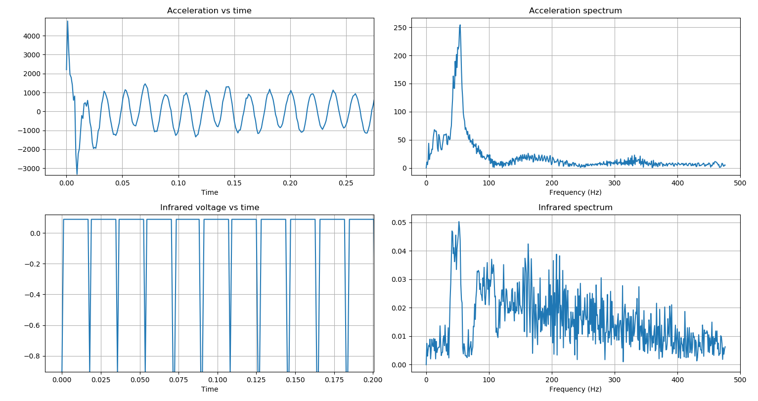
A single measurement is shown below;![]()
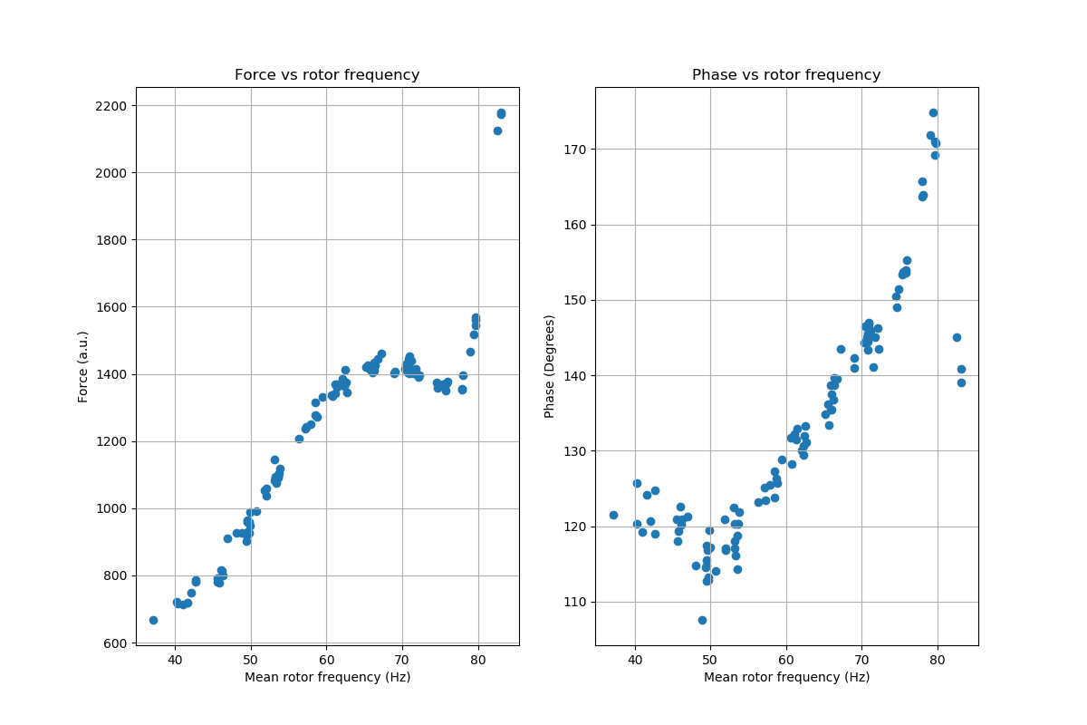
Multiple measurements are taken. For each measurement the amplitude of the accelerometer signal and phase difference between the IR sensor and the accelerometer signal are determined. As the phase seems dependent on frequency, the prism seems to have multiple plane unbalance, What also seems to play a role is that the electric motor works in reverse. The spinning disk probably creates current in the motor which is turned off. In the future, I will try to substract the measurements of unbalanced prism with a balanced one... Maybe their difference will be more intuitive.
![]()
The code, measurements and a brief discussion of the results are available on Github.
-
rotor stabilization experiments
01/10/2020 at 14:54 • 0 commentsOne of the challenges still open is how to balance the prism. Earlier, I discussed the mechanics in a blog named prism balancing. In this blog, I want to give a practical example of how to determine the mass and position from measurements.
Vibrations caused by a spinning rotor are measured with an accelerometer. As sensor, I used the MMA8452Q but would recommend the MMA8451Q or LIS3DH as they have better specs. I used the Raspberry Pi 3B to measure the signal and generated a signal for the polygon motor via hardware pwm using pigpiod.
I pulsed the rotor at 20 Hertz and recorded the vibrations for 1 second at 800 Hertz sampling frequency.
Sampling of the signal must be equidistant or otherwise the discrete Fourier transform can not be calculated. As mirror motor, I used the Panasonic AN4000A.
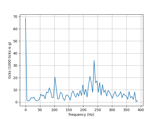
The discrete Fourier transform of a balanced mirror, shipped with the motor, is shown below![]()
There is a peak around 100 Hertz. The discrete Fourier transform of one of the prism I use is shown below.
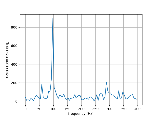
![]()
An enormous peak close to 100 Hertz can be seen. This amplitude can be compared to the amplitude of a known balance weight to determine the required mass. As the centripetal force is linear proportional to mass. This procedure is only so simple for single plane balancing, in two plane balancing the procedure is more complicated.
To determine the position of the mass, the position of the rotor must be measured. For example by using a photo tachometer. Earlier, I discussed how a camera can be used to measure the position of the rotor. A camera is quite expensive and it would require some image analysis.
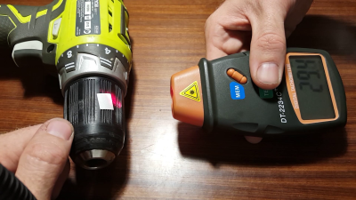
The DT2234C+ photo tachometer only costs 18 dollars. It was also discussed widely on Hackaday.![]()
As a result, I bought one and did a couple of experiments with it and attached reflective tape to one of the corners of the prism. The photo tachometer measured a speed of 5750 rpm, i.e. 96 Hertz.
This corresponds to my measurements as I can see a peak near 100 Hertz.
This also explains why I have so many problems with this motor and recommend the Sharp 160.
The Sharp 160 is able to spin at 2000 RPM. Also the relation between pulse frequency to the motor and the final RPM is direct. Pulsed at 20 Hertz the Sharp would spin at 1200 RPM and not 5750 RPM.
The position of the peak in the cross-correlation of the accelerometer and photo tachometer will be an estimate of the phase difference.
If I know the phase-difference with respect to the marking used by the photo-tachometer, I can use that to calculate the position of the balance weight.
The code used for the measurements can be found on Github. I also did a successful experiment with an artificial signal to calculate the cross correlation.
I still have to extract the signal from the photo tachometer and turn on the photo tachometer digitally instead of with a button. Also, I have to order balance weight. Ben Wishoshavich pointed out I could use armature balance putty. -
FPGA: hexastorm + icestorm
01/03/2020 at 12:26 • 2 commentsThe last weeks, I have been doing experiments to see if I can replace the programmable realtime unit on the Beaglebone with a FPGA. On the Beaglebone, there are two programmable real time units, which are very similar to micro-controllers, running at 200 MHZ with 8K byte memory per core and 12K byte shared between them. At the moment, I use one PRU and one memory of 8K byte which acts as a ring buffer.
There are some challenges with the current design. I am locked into the AM335x processor which runs at 1 GHz and is single core. The latest Raspberry 4 runs at 1.5 GHz and is quad core.
If I am able to build an extension for the Raspberry it would not be hard to use the scanner with other boards, e.g. the edge TPU or the NVidia nano.
When I started this project, I actually tried to do this with the Spartan 6 FPGA, using the Xula-LX25.
In the end, I managed to get something to work by writing the laser data to a sdram and then reading this data from the sdram. This was all written in MyHDL, see Github.
MyHDL is converted to verilog and this can then be converted to a bitstream by the Xilinx Ise.
In my latest experiments, I used the IceZero with the ICE40HX4K and Migen. The oscillator on the Icezero runs at 100 MHz and the ICE40HX4k has 81920 bits of memory. In practice, the memory is larger as the Icestorm toolchain is able to program the ICE40HX4k as a ICE40HX8k.
The ICE40HX8k is a lot less powerful than the Spartan 6. It has 1/6 of the SRAM memory and 1/3 of the LUT. The main advantage for me is the open source icestorm toolchain which runs on linux.
My current setup works as follows. Data is streamed to the FPGA via SPI and stored on the FPGA using the internal SRAM. The sram is used as a buffer before the data is placed on the substrate with the laser. My code can be found here, especially look at the spimemmap example.
I did some experiments on the Raspberry 3 using Python and Spidev and I am able to get data rates up to 25 megabit per second.
In my current laser head, the scan line is 8 mm long and a pixel is 10 micrometers. So there are roughly 800 pixels per line, i.e 100 byte per line. At 20.000 RPM * 4 (facets)/ 60 = 1333 lines per second. This implies 133 kB/s or 1 megabit per second, much less than 25 megabit per second.
Another problem, I am still working on is balancing the prism. I hope to report some progress on that soon.
What might be of interest is that MIT recently released a press statement in which they show that they are working with lasers and ultrasound. The technology is very similar to my previous blog post. The only difference is that they use a laser to detect the vibrations.
Another interesting was one by blog the drive. There apparently is a Dutch startup which use lasers to clean railway tracks. -
hackaday supercon
11/16/2019 at 22:03 • 0 comments![]()
Won the honorable mention for best communication; 3000 dollars and a lot of branding. It was great to meet you all! Thanks for the award! You can also find this room in the supply frame video, door is opened at 0:44 see video.
-
photoacoustic effect
11/07/2019 at 12:32 • 0 commentsRecently, I was reading Hacker news and realized I hadn't created prior art in the field of photo-acoustic imaging.
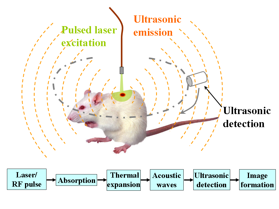
The photoacoustic effect or optoacoustic effect is the formation of sound waves following light absorption in a material sample.Basically the schema is as follows; you scan with a laser beam over tissue or gas and then detect the produced sound waves. From it you can determine the material properties.
![]()
The effect was discovered by Graham Bell in 1880. A general patent by Hitachi can be found here US5781294A. The claim is quite nice and general but the patent expired in 2012.
Olympus corp filed a patent for using this effect with a galvo scanner. The patent is valid up to 2035 and its number is US10209226B2. Let's have a look at claim one;
"... the scanning unit includes a movable mirror which changes an angle of incidence of the excitation light incident on the objective lens, and ... "
Prior art is constructed as follows;
"... the scanning unit includes a scanning prism which changes an angle of incidence of the excitation light incident on the objective lens, and ... "
A more complicated patent example from 2018 with two beams by Yokogawa electric corporation can be found here US20180140199A1 .
As we can see the patent propose the use of two frequency shifted beams from the same light source which are then coupled into a single point by a variable focus lens.
However, what is also clear is that this lens is positioned after the light scanning unit. I claim that the lens is positioned before the light scanning unit in a prism scanner. This was not obvious to the claimant as it obviously thought of the light scanning unit being a galvo scanner or a rotating mirror.I claim the reverse effect. So here an ultrasound wave is produced and the result is detected via an interferometer which uses a scanning prism. The idea is similar to the optical coherance tomography setup I discussed earlier. A patent by Hitachi can be found here US20130160552A1 but it expired as they seem to have stopped paying the fee.
A Dutch research group from the TU Twente used the effect to detect breast cancer. The optical effect is non-invasive but does not have a deep penetration depth. I claim the same but then for a scanning prism and also other forms of skin cancer, skin deseases, cancer etc.
Now when I think of it.. the TU Twente also built the Brandaris 128. It is a fast imaging camera which use a rotating mirror at 1.2 million RPM see http://stilton.tnw.utwente.nl/people/michel/Michel_Versluis/Brandaris_128.html.
This was an experimental project so I don't believe you can buy one commercially. Cordin does sell them and they have mirrors rotating at 5000 RPS which is like 300.000 RPM. This is quite nice as it serves as an example of how fast prisms could rotate. These cameras with rotating mirrors are used in research and have been used to detect nuclear explosions etc.
-
Update
10/31/2019 at 10:54 • 0 commentsHey all,
I thought it was nice to give some update on the progress. Most of the work I did was in the software domain.- beaglebone now works with cape universal and not with a predefined cape
pins can be changed on the fly without booting linux. - if the machine turned on the laser turned on as well, the startup procedure has been changed so the laser doesn't turn on by accident
- in the proof of concept experiment, the laser module was turned off after each lane and turned on before a new lane. With the new software you can continue to expose without turning of and on the scan head.
- the c++ library for the TMC2130 stepper has been wrapped in python
- I have added the possibility to expose with a single facet. In my earlier post, I outlined this can be done via the facet times. I have however chosen to do this by an internal counter which simple counts the facets and assumes a facet is never lost.
- variables are now centralized in one location. They used to be sprinkled all over the place. You don't need to recompile the assembly to change the variables of the scanner
- The assembly code of the scanner and the python code have been refactored. I would say the code is much more readable now
- The spinup state changed. The laser is spin up and then it is tested whether it passes a threshold check. The laser turn on time is however much smaller than this threshold. This used to be the same.
I have also build a second laser module and fixed the z-endstop in my test setup.
As always let's create some more prior art;
Blackbelt has a patent called for an infinite conveyor belt printer see https://patents.google.com/patent/NL2018728B1. This was scrutinized by Hackaday. The patent so far only seems valid in the Netherlands and the conveyor belt has to be planar with the horizon, see words ".. parallel met de horizontaal is gelegen..." at the end of claim 1.
As such, I claim a machine in which the belt is not planar to the horizon but under a tilt angle.
I claim an infinite conveyor belt printer in which both a laser head and extruder is mounted. Possibly the extruder deposits a polymer which is polymerized by the laser. This polymer can be viscous so it stays on its place.I also claim the use of a prism scanner in data gloves. This can be used to write or read from a substrate from a glove. I earlier claimed the Hexastorm was connected to a robotic arm like the Dexter.
In industry 4.0, workers are equipped with data gloves to check wether they are operating within requirement. In the proglove as shown here https://www.proglove.com/ a camera is added to the hands of an operator. I can imagine a prism scanner is placed in this data glove. This prism scanner could record information or write information on substrates. It could detect biological markers, or QR codes. It could detect cells or give a marking to a product. It could be used to determine the final position of a product which has to be precisely placed. - beaglebone now works with cape universal and not with a predefined cape
-
Hackaday prize 2019
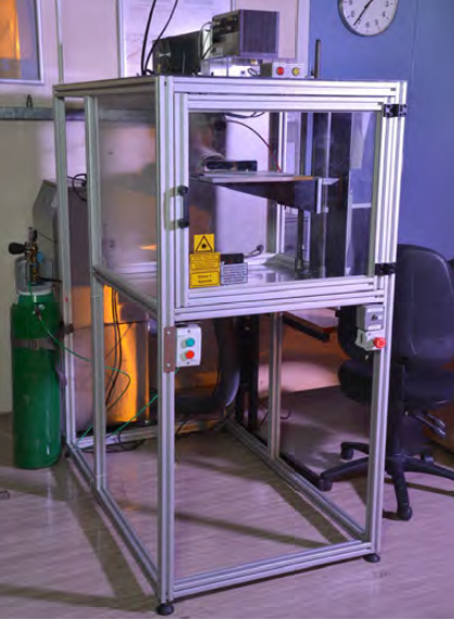
09/29/2019 at 14:15 • 2 commentsUploaded my submission for the Hackaday Prize 2019. Thanks for watching!
 Hexastorm
 The laser allows one to locally tune the diffusion of colorant into the textile.