-
Facet times
09/26/2019 at 16:22 • 0 commentsGood news! I received the NBC31111. The facet times look to be good and the motor is quiet again.
In other words; the laser module is working once more.
I have quite a busy weekend ahead, but will try to make a new exposure on Monday.The facet times are;
Note that i ignore the first 100 lines as the prism doesn't seem to be stable enough.
output from script:
---------------------------------In total, sent 1600 lines
Error received; ERROR_NONE
The expected hsync time is 12500
The facet series are
Item: 100
12592 12590 12589 12592 12592
12395 12396 12395 12396 12395
12408 12408 12410 12410 12409
12594 12597 12596 12596 12597
Item: 116
12592 12591 12590 12592 12593
12395 12396 12396 12395 12395
12409 12409 12410 12410 12408
12597 12597 12595 12595 12597
Item: 132
12593 12590 12589 12593 12592
12395 12396 12396 12395 12395
12408 12409 12410 12409 12408
12597 12598 12595 12596 12598
Item: 148
12592 12589 12591 12593 12590
12395 12396 12396 12395 12396
12408 12410 12410 12409 12409
12598 12597 12595 12596 12597
Item: 164
12590 12590 12592 12591 12589
12396 12396 12396 12396 12396
12409 12410 12409 12409 12410
12597 12595 12596 12597 12597
Item: 180
12589 12591 12593 12590 12589
12396 12396 12395 12395 12396
12410 12410 12408 12410 12410
12597 12594 12598 12598 12595
Item: 196
12589 12592 12590 12590 12593
12396 12396 12396 12396 12396
12410 12409 12410 12410 12409
12595 12596 12597 12595 12595
Item: 212
12593 12592 12589 12593 12591
12396 12395 12396 12395 12396
12409 12409 12410 12409 12409
12595 12597 12595 12596 12597
The counters are [376, 1123]
Test passed, can bin all times-------------------------------------------------
Earlier, I reported that the facet times recorded by the diode can be used to determine the facet number. In the above, you can see that one facet has facet times smaller than 12400.
If the jitter allow per period is set very small, no difference can be perceived in facet times. For the proof of concept module, I used a jitter allow of 1/3200. All the facet times are then very similar and jitter is quite minimal.
With a jitter allow of 1/100, I can determine the facet and use an interpolation table to reduce the jitter.
I am not sure which strategy works best, but I do claim I possibly use one of these methods.
I also claim I use information by an acceleration sensor to determine whether my prism is rotating smoothly or an earthquake is interrupting operation. I also claim I use this information to correct the data sent to the prism scanner by calculating a more accurate position. -
Prism balancing; determining the rotor position
09/25/2019 at 13:38 • 0 commentsEarlier I discussed that the prism ideally is balanced and how this could be done.
The acceleration and position of the prism needs to be measured during rotation.
The first step is determining the position of the prism, i.e. rotor. Two options were considered; detecting a marker with laser or detecting a marker with a camera. I went for a camera as it seemed more robust.
Also, the position of the weights needed for balancing can be visualized with the camera.
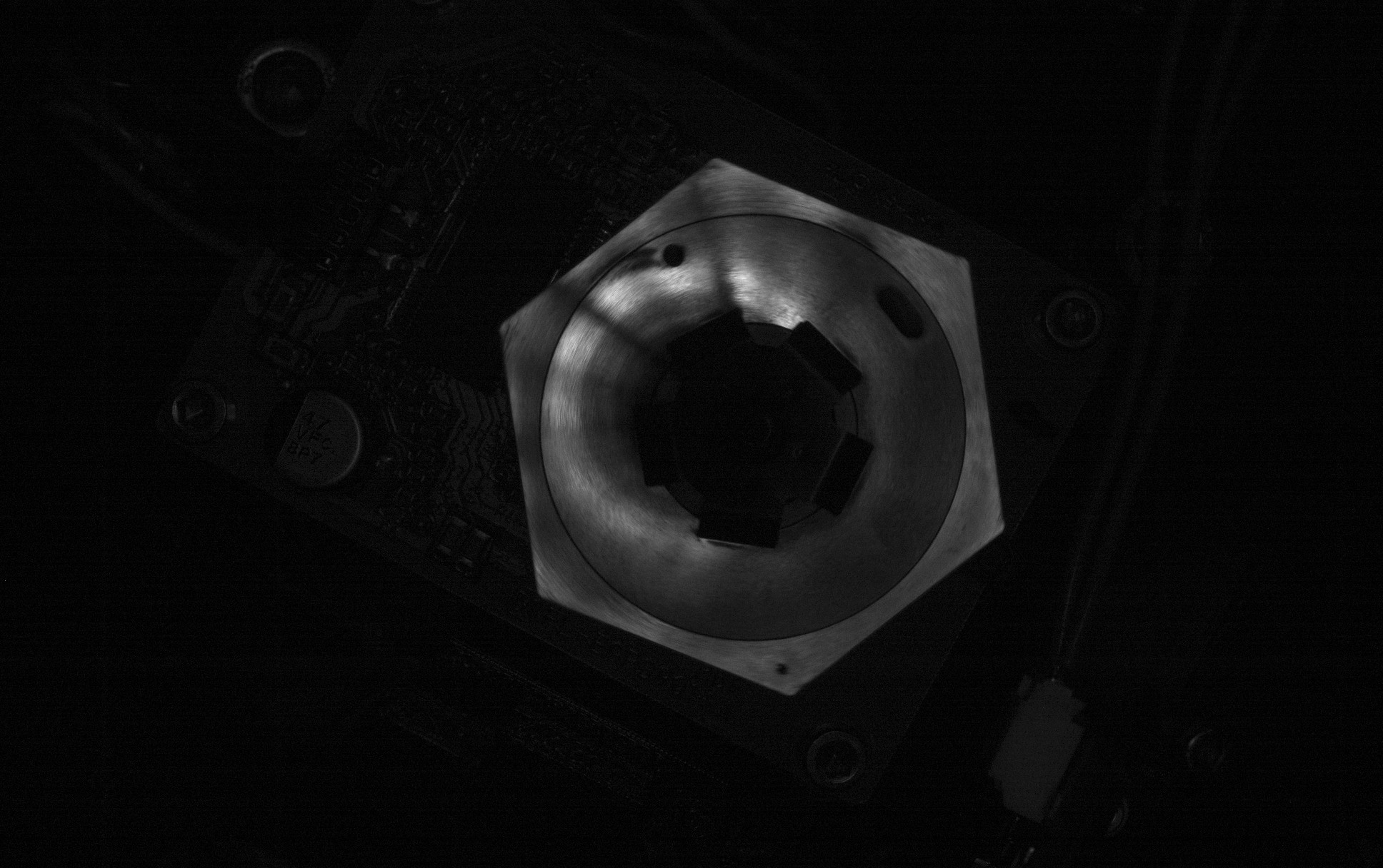
In specific, the UI3060-m-GL, specs are; USB 3.0, CMOS, 166.0 fps, 1936 x 1216, 2.35 MPix, 1/1.2", Sony, Global Shutter. I used a shutter time of 0.019 milliseconds and a ring light illumination. Having a camera with a global shutter is key, rolling shutter cameras I tried didn't work.. Initially, I thought the ring light would be useful as strobe light but the camera has so short exposure times it just needs additional light. I am planning on building a dedicated setup, see github, but used the current laser module for the test.
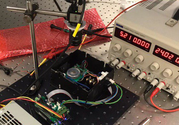
The setup is as follows;Camera exposes from the top using a lens with a focal length of 12 mm, ring light is given 24 volt via power supply.
![]()
As you can see I used the mirror and not the prism. The mirror is already balanced and can go up to 21000 RPM making it better for exposure tests.
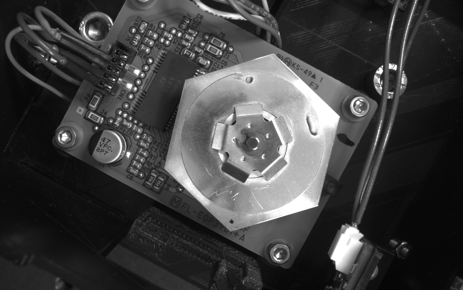
At 0 revolutions per minute the mirror looks as follows with auto exposure settings;![]()
I did not modify the mirror. In the ring you can see two markings. This is the weight used to balance the prism. The outer black dot, outside the ring, seems to be made with a marker. This seems to be used to determine the position of the rotor.
At 21000 revolutions per minute the mirror looks as follows with 0.019 ms exposure time;
You can see a reflection of the ring light as the illumination is not really proper. In the final setup, I should use a better diffuser so you don't see the positions of each led.![]() Next, I will see if I can determine the force on the bearing during rotation. Then, I will need to relate the two signals and see if I can balance those prisms :-).
Next, I will see if I can determine the force on the bearing during rotation. Then, I will need to relate the two signals and see if I can balance those prisms :-). -
Status
09/23/2019 at 15:35 • 0 comments- uploaded a video for the Hackaday Prize 2019.
- made a pitch which is more suited for business case minded people
- still waiting for the delivery of new NBC3111 mirror motors as I have broken mine. The new setup "works" but is not practical without these mirror motors. The prism makes much more noise and can converge into two modes. As a result, the prism has to be restarted 50 percent of the time. The noise reduces at lower speed but the two modes remain. This was not the case with the NBC3111 which had a flawless operation at higher speeds. I have therefore decided to focus on balancing the prisms for now and waiting for the NBC3111. The new motors should arrive somewhere next week.
The current plan for the prism balancing setup is that I will use a MMA8452Q to read out the acceleration. The position of the prism is monitored using a marker and a stroboscopic camera.
Additional claims;
I also claim the use of prism in the industry of thermal plate setters.
Another patent by Apple has been revealed for scanning mirrors, see display device US2019/0285897A1. I also claim this patent but than for the case of scanning prism. -
Video of the alignment setup
09/12/2019 at 19:48 • 0 commentsI wanted to share a quick video of the alignment setup. The prism is running 2.5 times slower than in the proof of concept model. I have also removed the cylinder lenses for now as this simplifies alignment. The focus is on a robust setup for demonstrations and later quality.
As always, lets generate some more prior art;
non-planar 3D printing with prism scanner to avoid situation like the one with US10005126B2
I can envision a liquid or viscous fluid is applied with an extrusion nozzle or inkjet head and is cured with the prism scanner. This could also be a viscous liquid applied with a blade.
The patent talks of a correction factor that is calculated on basis of the slope. This is done to alter the extrusion. I claim that an optical measurement is done of the substrate to determine the correction factor (so it is done from life data during the experiment not from already existing cad data!!)
I claim that the amount of liquid that is extruded is constant (this is not altered). The prism scanner decides which part of the liquid is solidified. The remainder is possibly sucked up with a squeegee and pump or applicator bar and pump.
I can envision a similar process but then one were powder is blown and then sintered with a laser guided with the prism.I can envision this is done in a hospital setup to a human or in an operation or for inspection of mechanical parts. I also claim the area "food printing". You can for instance cure egg whites with IR radiation to trigger or monitor a Maillard reaction.
I claim belt like printing with prism scanner (so you print on a rotating belt, e.g. blackbelt 3D).
I also claim that a prism scanner is used to check the indentation in a hardness tester, at the moment a lot of companies use a camera. I claim that a prism scanner is used to check the indentation, for example see the hardness testers by Innovatest Europe. -
Hackaday prize semi-finalist!
09/10/2019 at 20:47 • 0 commentsHey all,
I made it to the Hackaday Prize 2019 semi-finals! I am really happy with the feedback from the community and the honor to be among these twenty amazing finalists out of these even more amazing applications. I have seen great projects on Hackaday; not only in this contest but in general. The two most related to my project that were featured on this site are; OpenExposer and Ldgraphy.
The best thing is that Hackaday gives me an even bigger excuse to work on the project.
I aim to show once more that I have a working prototype and will try to create PCBs. These results can then hopefully be used for the final video. I will also try to make a brief technical presentation.
In the 3D printing realms the most important patent I am able to circumvent is US9079355; the scanning mirror patent by Envisiontec which is valid up to 2033.
I have mentioned others. Recently, I got informed that Apple Computers filed a patent for a Scanning Mirror Display Devices. It's a virtual reality set, like the Fiber Scanning Display I discussed earlier from Magic Leap.
Obviously; I claim everything, including the fancy pictures and sensors, Apple Computer claims but than for "Scanning Prism Display Devices" I call this prior art, see my earlier blog.but let's continue with that prototype now...
-
Current Status
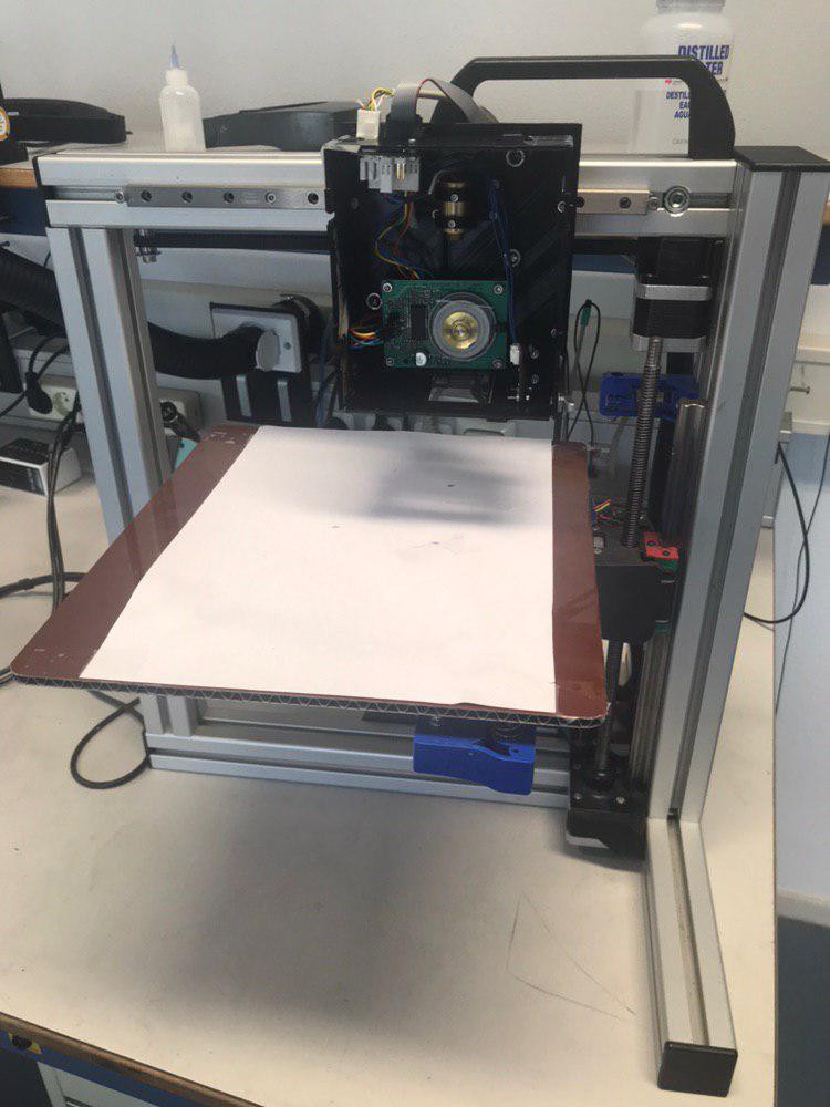
09/06/2019 at 13:40 • 0 commentsJust a quick update; I have mounted the laser head back on the frame. All the electronics work and the machine is good for a few tests. As said, I have removed the cylinder lenses to increase ease of use. Due to a wiring error I blew up the polygon motor with chip NBC3111, I have replaced the polygon motor with motor with the chip Panasonic AN4000A. This motor produces a lot more noise at the same speed. It can effect future measurement, I have ordered new ones but have to wait 2 weeks.
The white paper placed on the build plate is to mark the area needed by the scanner. You can see a blue markings for that. A laser head has a greater height tolerance than a 3D printer nozzle, so leveling is not really an issue. The laser is far out of focus here, the head is typically closer to the paper.![]()
-
Facet detection using facet times
09/03/2019 at 10:41 • 0 commentsIn my previous logs, I outlined that the cross scan error is well understood and can be kept less than 40 micrometers. The solution is to keep the spot very close to the facet, so the deviation due to the prism wedge is minimal. In future versions, five times more accurate prisms are used so the deviation should be much less than 40 microns.
In the log titled jitter, I outlined that the facet overlay in time can be a challenge. Although this was not the case for the proof of concept version. Let's present a solution;
For each facet the microprocessor calculates using the photo-diode signal how many ticks it takes per facet. There are about 12500 ticks per facet, so ideally you would always get 12500 ticks.
If i look at the a sequence of the first 16 facets I see;12468, 12590, 12579, 12347
12473, 12591, 12581, 12349
12472, 12591, 12581, 12348
12472, 12591, 12580, 12348Here, I ordered the times already in groups of four. It is immediately clear that you can bin the facet by times. Especially, the fourth facet in each row seems suited for a bin.
You can also calculate that the sum of the first group is is 49984, roughly 4X12500 = 5000.
If I take the bin with lower limit 12340 and upper limit 1360, I get 200 items over 800 facets.
The binning seems perfect; there are no outliers.One could think that setting the counter to zero and illuminating after a certain time should give zero jitter. In practice, there are limitations as the spot speed is not constant over a line and there might be other aberrations.
You could also correct for the cross scan error once you have detected the facet but you might end up with a non-uniform dosage. This is quite critical if you are using multi-patterning techniques.*** experimental remark ***
Too complicate stuff, a few days later I found out that I could get all the facet times equal. If make the jitter error very low, e.g. 1/3000, I am not able to detect facets; their times are too close.
I had to modify the code a bit for this to pass the hsync threshold. I didn't do this earlier so therefore didn't see this. This was needed when I blew up the polygon motor and replaced it with the panasonic one. I thought I could see jitter but will ignore this for now and use like 1/200 of period and continue with one facet
****Although, I could add an interpolation table to the algorithm. I will simply start with one facet and try to expose PCBs.
What further might be of interest to the reader is that I have also created some prior art in the field of door detection systems. A good example of a scanning mirror patent is EP1470314B1.
Claim one reads; " ... which operates according to the reflection principle and has the purpose of monitoring a region assigned to one of the approach areas, by means of a detector beam for obstructing objects ... ".
Prior art is constructed by claiming the same claim but than on basis of the refraction principle. I also claim all the areas where the Belgian company Bea Sensors uses reflective polygon scanners, e.g. the LRZ-H100 and opening & safety sensor for barriers. -
Jitter
08/27/2019 at 21:12 • 0 commentsThe new box works quite well.
At the moment, there is one key issue. The jitter is too large; as you can see below.
I am also not happy about the glow to the right but that's a simple alignment issue due to reflections in the prism. I changed the offset and height of the diode. As long as the spot passes the diode in the middle, the pattern remains the same. My current algorithm of simply setting the counter to zero if the photo diode is passed might be too easy. The spot changes speed while scanning. This might alter measurements. In the coming days, I will try if i can detect different facet times for each facet. I could then label facets and fix it with a timing table.The cross scan error is low and comparable to earlier versions.
The photo diode cap is no longer needed. This seems to be due to the op-amp, Schmitt trigger circuit.In the picture below a pixel is 4.8 micron.
Earlier results were much nicer, see earlier blog jitter removed, but you can learn a lot from the “bad” ones too.
![]()
-
Prism balancing
08/27/2019 at 14:10 • 0 commentsRecently, I removed the technical presentation from 2017 as it is completely outdated.
One of the things I haven't outlined so far is how to balance the prism.First let's recall the centripetal force;
Unbalanced rotating masses or rotors have relatively high force effects on bearings. High level of unbalance can cause vibration and deformation.
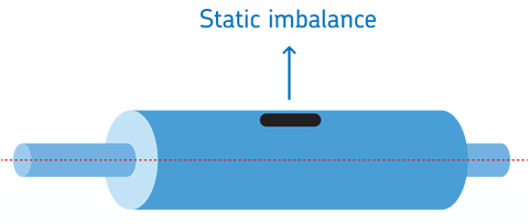
Two types of unbalance can be distinguished; static unbalance and coupled unbalance.
In static unbalance, there is only an unbalance in a single plane![]()
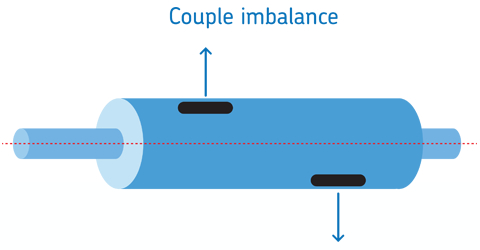
Coupled unbalance occurs if there is a static balance in multiple planes but there still is a net force acting on the rod.
![]()
In reality all unbalance is a combination of the two and therewith called dynamic unbalance.
As the prism is quite thin and shaped like a disk, it is assumed there is only static unbalance.
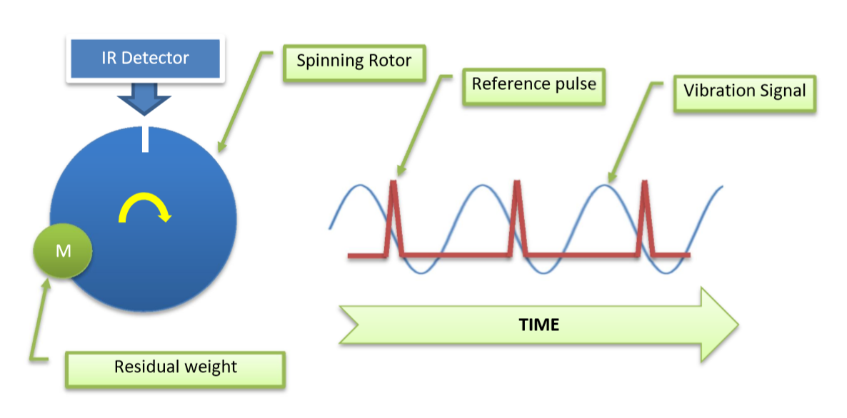
The prism can be statically balanced by placing a reference weight 180 degrees before or opposite to the center of weight which is causing the unbalance (see coupled unbalance and note that here they are assumed to be in the same plane).To measure the unbalance typically a setup as shown below is made;
![]()
The rotor is spun and a reference weight is placed on top of the rotor. This will now be the primary unbalance. A trigger is recorded for each rotation. Also a signal from an accelerometer is recorded. The accelerometer signal can now be converted to the amount of mass needed in grams and the position in degrees.
The residual weight is removed and the rotor is spun. This signal is used is to calculate the correct reference weight and position.
For a prism system, the top of the prism could be partly blackened. This would than block a laser if it shines through from the top while the prism is rotating. This signal could then be used to balance the prism.
If multiple prisms are balanced, most likely the reference mass only has to be placed once. As all systems are quite similar.References:
1. Vortex: Dynamic Balancer and Vibration analyzer of Dynex hobby
2. Mechanics of Textile machinery NPTEL, in specific the chapter on Balancing of Machines (page 140) -
Nearing minimum viable product
08/21/2019 at 22:07 • 0 commentsThe laser module is nearing a stage of what I believe could be a minimum viable product. The customer has to decide on this though. The earlier design in Freecad was upgraded to a closed box using the Freecad LCInterlocking module.
The copper laser module has been removed from the housing to safe cost and space. The laser was also not in the center of the black housing which is a problem with alignment.
The MVP will be sold without two cylinder lenses, this saves space and reduces cost.
A user can then upgrade afterwards. The cross scan error can be kept low by keeping the focus point near the exit of the box. The final version will also feature prism with edges parallel to <1 arcminutes instead of <5 arcminutes.A top front view of the system.
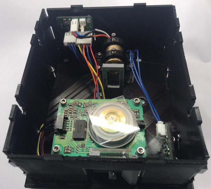
![]()
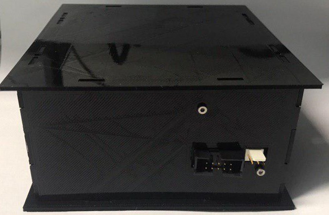
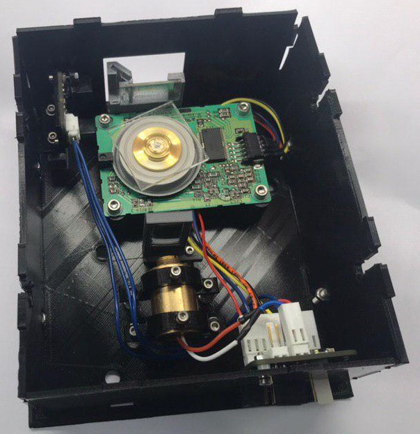
A top view from the system from the reference point of the laser. A mirror can be seen that is used to redirect the laser to the photo-diode which is protected by a black cap.![]() The module is quite small, 140x130x60 mm. The back has two connectors one plug for power; 12V, 5V and GND. The other plug is for a ribbon signal cable.
The module is quite small, 140x130x60 mm. The back has two connectors one plug for power; 12V, 5V and GND. The other plug is for a ribbon signal cable. ![]()
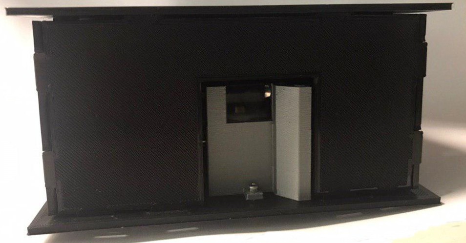
In the front only a small opening is left for the laser bundle. The scan line is typically in the order of 8 mm. Possibly, in a future version an automated shutter is added so it can be protected from dust.![]()
The product shown is close the minimum viable product I plan to release. I am making a second module and will then demonstrate the technology by making a PCB.
Hereafter, I intend to test market appetite for the technology and see if there is demand for 10 units. Another approach would be to measure metrics like likes or views of the video.
 Hexastorm
 Next, I will see if I can determine the force on the bearing during rotation. Then, I will need to relate the two signals and see if I can balance those prisms :-).

 The module is quite small, 140x130x60 mm. The back has two connectors one plug for power; 12V, 5V and GND. The other plug is for a ribbon signal cable.