-
Form 3
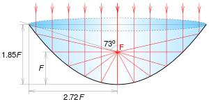
04/02/2019 at 18:48 • 0 commentsFormlabs launched the Form 3 . It uses a parabolic mirror and a galvo mirror. The galvo-mirror is used to obtain a constant line speed as they don't use an f-theta lens. The parabolic mirror is used to get the spot into focus over the full scanline.
The galvo mirror can be seen here;
![]() The properties of a parabolic mirror are shown below;
The properties of a parabolic mirror are shown below;![]() The optical system will produce a better spot quality than their previous galvo design without f-theta lens.
The optical system will produce a better spot quality than their previous galvo design without f-theta lens.
In comparison with the Hexastorm;
Advantages;
- no cross scan errors / jitter
- long scan line
- scanhead has to be moved in only one direction, not two
Disadvantages;
- low scan speed; don't use rotating mirror
- diffraction limited spotsize is given by 2w0 = 4 lambda / pi * f/d
In the Hexastorm, the focal lengths are very short. It for sure is able to produce a smaller spot size.
- elliptical correction; seems unlikely that Formlabs is able to circularize the beam.
Form 3 spotsize is 80 micron. For both SLA and SLS a smaller spot size then that does not seem required. There are systems which use higher resolutions.
A difference with the Form 2 will be that a part will be less smooth. Tracing the outline gives smoother results. Lines imply a discretization in one direction. It can also not employ writing strategies to cure parts. This can be used to mitigate shrinkage. Reflective lenses give errors due to fabrication faults, e.g. some sort of mustage error; the line is not straight.
Reflective optics are better with high power lasers, e.g. 10 kW lasers. Refractive optics have the problem of thermal lensing. Up to 1 kW you can still use Zinc Sulfide / Zinc Selenide beyond that you want to grab some mirrors (ref DOI: 10.1117/12.2037356 )
Form 3 is 3,499 and begins shipping in June. While the 3L is 9,999 and ship near end of the year.
Their system probably has a safety clearance for lasers of class 3B. This would allow them to ship up to 500 mW. For some reason they only use 250 mW. -
Road ahead
02/28/2019 at 16:50 • 0 commentsI see multiple applications for the Hexastorm. I have explored a vertical sales model where I cater the specifications of the scanhead to the needs of an industrial customer. The challenge with this model is that industrial clients require exclusivity and there are still adoption costs.
This is hard as I also want to use the technology in different markets and have a preference for open-hardware.
Considering possible beach head markets (SLS, SLA, advanced ceramics, mircro-sla, bioprinting or CLIP-like, i.e. carbon 3D like technology), I have come to the conclusion that the PCB prototyping market has the lowest barrier for entry. 3D printing processes require multiple layers, a customer need which is best served by a fast illumination. This is possible but will drive costs. In addition, it requires some sort of layer application method which is hard to implement in the current setup.
The current setup is not ideal for PCB prototyping. It is not possible to cut out a board and there are some obvious safety and maturity issues with the current machine.
As such for a PCB prototype, you would currently need two machines which have to be cross-aligned.
I plan to address the first issue and will add a spindle to the setup. At the moment, I am thinking about a 775 DC motor with RPMs between 3000 and 9000. They are quite cheap and great for a first test. The software can then be partly copied from Machinekit or Zeller's BeagleG. Personally, I think t-belt will suffice for the x- and y-stage. The scan-head is already fast enough at low stage-speeds for a dual layer PCB. Besides PCB prototyping, the developed software could also be useful for bio-printing due its ability to parse G-code. The problem with current UV exposure methods in bio-printing is that they typically rely on a non-precise UV light source for resin curing.
The mechanical design and dimensions have to be determined later. Bungard sells the following board sizes; 100x160 mm, 210x300 mm and 510x1150 mm. They seem to be industrial standards. I think 210x300 mm should be feasible.
In the following, I would like to make a remark with respect to Carbon 3D and Nanoscribe. Carbon 3D initially patented Continuous Liquid Interface Processing (CLIP) see patent WO2014126837A2. The company currently seems to sell it as Digital Light Synthesis (DLS) technology and makes a more general claim; an AM process with oxygen inhibition. Given my current knowledge of its patent portfolio this seems too wide. In the patent it claims that the part moves continuously away. This does not have to be the case. It would be more likely given a laser-scanner that the part does not move continuously away. You could expose a line multiple times and cannot illuminate a complete cross-section at once. It would circumvent the patent and the resulting parts might still be more flexible and have a higher z-accuracy than classical step-wise produced parts.
Nanoscribe uses dual photon polymerization with a galvo scanner as can be seen from reference 1. Optically, the advantage of the Hexastorm light module is its telecentric projection. This allows a machine to stitch lanes accurately without a telecenric lens. As such, it could be useful for a dual-photon process. Naturally, this would have to be elaborated further with an optical design.Reference;
1 https://nano.secure.pitt.edu/sites/default/files/Equipment-SOP/Nanoscribe%20user%20guide_0.pdf
-
FPGA code
02/27/2019 at 22:51 • 0 commentsUploaded my old FPGA code to Github; https://github.com/hstarmans/hexastorm_fpga .
If you are Hacker enthusiast and think you are capable of controlling laser scanners via FPGA.
This might give you a start! -
SLS machine
02/27/2019 at 21:43 • 0 commentsWith several industrial parties, I have discussed the possibilities of the Hexastorm in laser sintering, in specific powders.
Single mode laser diodes are expensive in the IR range. High power laser diodes are typically multi-mode. A possible supplier is Lumics.de . The diodes have a wavelength of 1 micrometer and a power between 3 and 7 W. It's assumed their price is in the order of 1K euro. You can pulse them at 20MHZ so they are suited for laser scanning. A problem is that these fibers are multi-mode lasers so the spot will not be so nice. The fibers have a diameter of 50 and 100 micron for 3 and 7 W respectively. I spoke to an expert and a spot of 100 micron should therefore be feasible as it is a 1 on 1 projection and the numerical aperture is not compressed a lot.
EOS spends uses a galvo system and C02 laser and the power is between 40W and 80W. EOS has a minimum feature size of 0.5 mm. Formlabs uses a fiberlaser with a galvo and something like 5-10W power. Hexastorm could provide that with one module.
To provide a viable commercial alternative for EOS, you can use 25 modules in parallel.
You would have a power of 75W or 175W. If we assume the price per module is 2K euro the total price would be 50K euro. You would also need a translation axis which is assumed to cost 5K euro. -
Exposure new scanhead
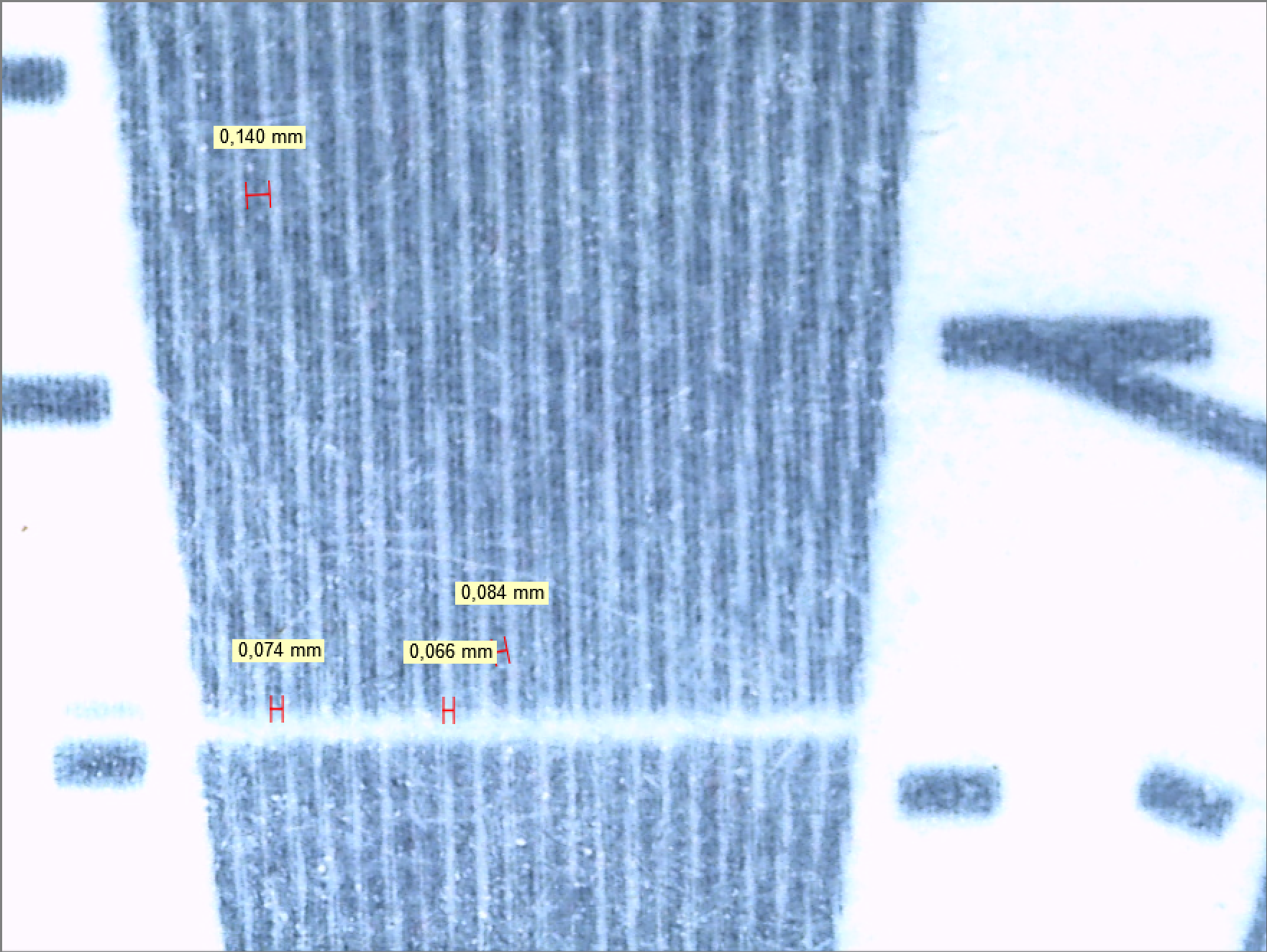
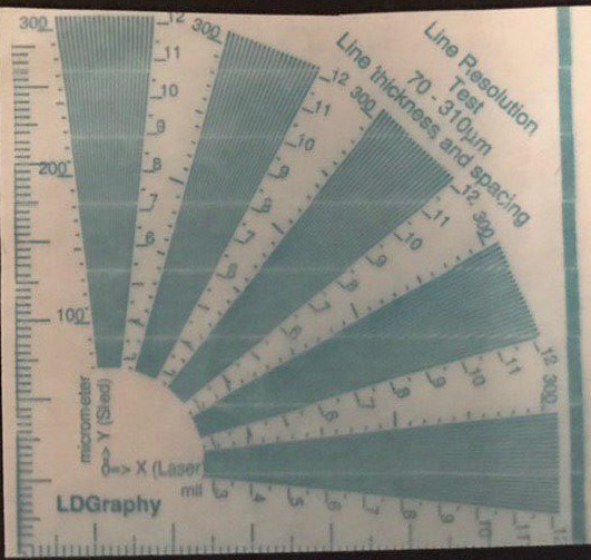
01/29/2019 at 21:40 • 0 commentsMade an exposure with the improved scanhead today. Results look good, already at 100 microns before optimizing, exposure speed is around 2 mm/s. Still need to fix the stitching error, it result in a white line.
Image was taken with a Leica DMS 1000. Machine is calibrated, measurements are accurate.
Full overview of sample shown above, taken with smart phone.
![]()
-
Stabilization accuracy
01/25/2019 at 14:47 • 0 commentsYesterday evening, I measured the stabilization accuracy of the scanhead. I repeated the following;
enable the scanhead, stabilize it (get it in sync) sent out pixel 3600 and record the image with an exposure time of 50 ms.
The result; spot is extremely stable. I measure a standard deviation over 21 measurements in the x- and y-direction of [0, 2.2] micron. Note that this is expected as the y-axis of the camera was parallel to the scanning direction. I have added the measurements as rar file, see 21measurements.rar.
Summarizing; repeatability in scanning direction after disable/enable scanhead is 2.2 micron. -
Jitter removed
01/23/2019 at 21:05 • 0 commentsI have been able to almost remove the jitter. I have added a prism to refract the light. Using the prism, I can position my diode closer to the focal point and ensure it is hit in the middle.
I also realigned the first lens. I used a UV light, bluepoint2, with Norland61 and UVacryl2295 for final fixing. The prism is 7.5x7.8x8 mm. It was still in stock. The single spot is 25x25 micron.
A spot created by four facets is 48x60 micron. The cross-scan error is 23 micron. The jitter is 35 micron. The facet error was set to 1/3200. In general, the lower the better.
I still need to measure the lane-to-lane stability if this is done, I will proceed with experiments.
In the image below a pixel is 4.8 micron. Note that the spot become less sharp at the edges, as predicted by my earlier theoretical calculations.![]()
The new setup with prism and photodiode.![]()
-
Jitter
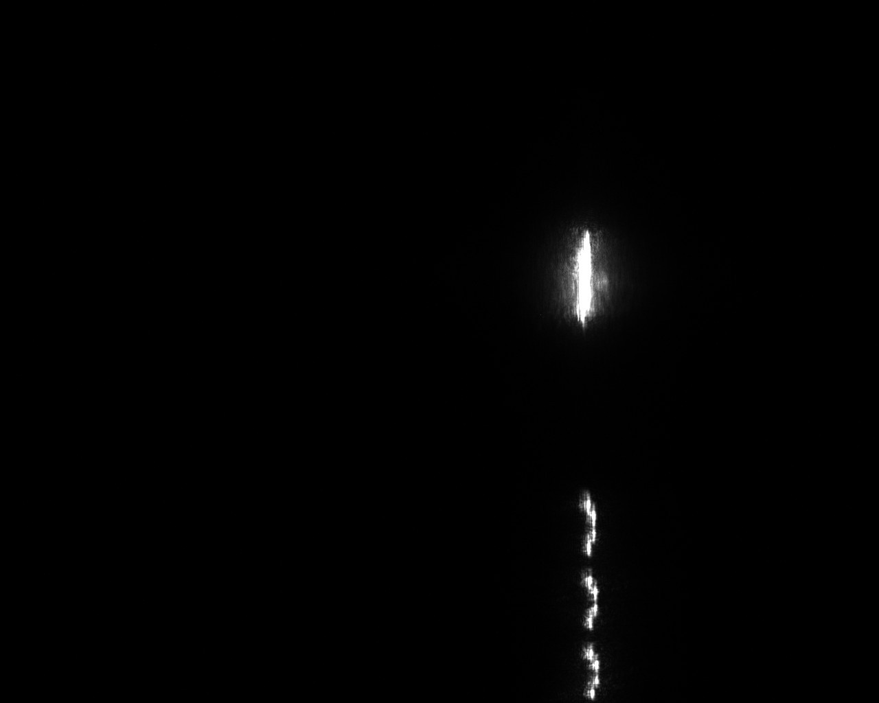
01/17/2019 at 17:32 • 0 commentsChecked the jitter today and it is pretty bad. The facets do not overlay each other in time.
With the current settings the pru measures a 1 percent error in time. I have been able to work with a 0.25 percent and a 0.16 percent variance in the current setup, see the constant JITTER_ALLOW in the header. However after gluing I couldn't get it back to 0.16 percent. Probably the photodiode is not hit in its sweet spot.
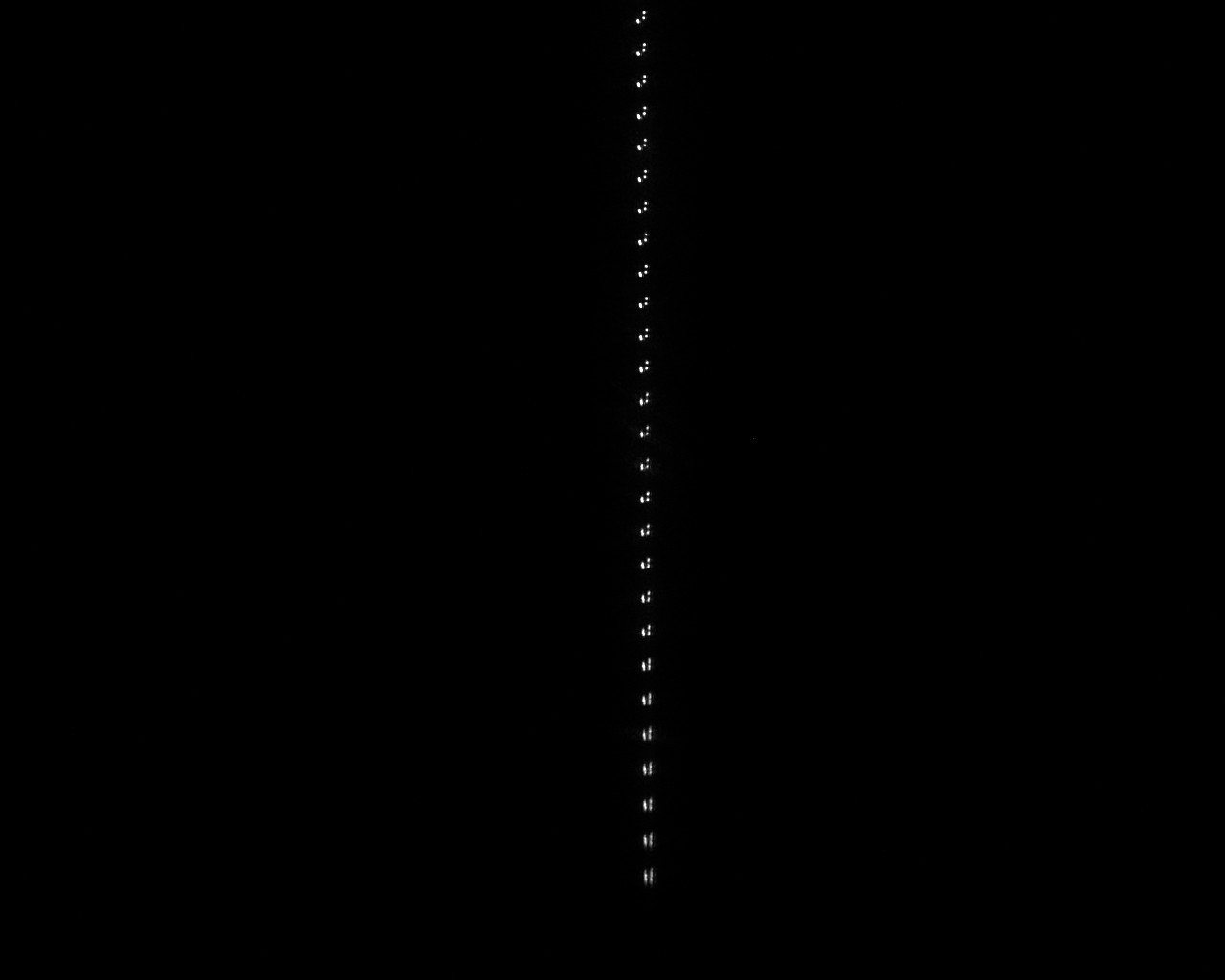
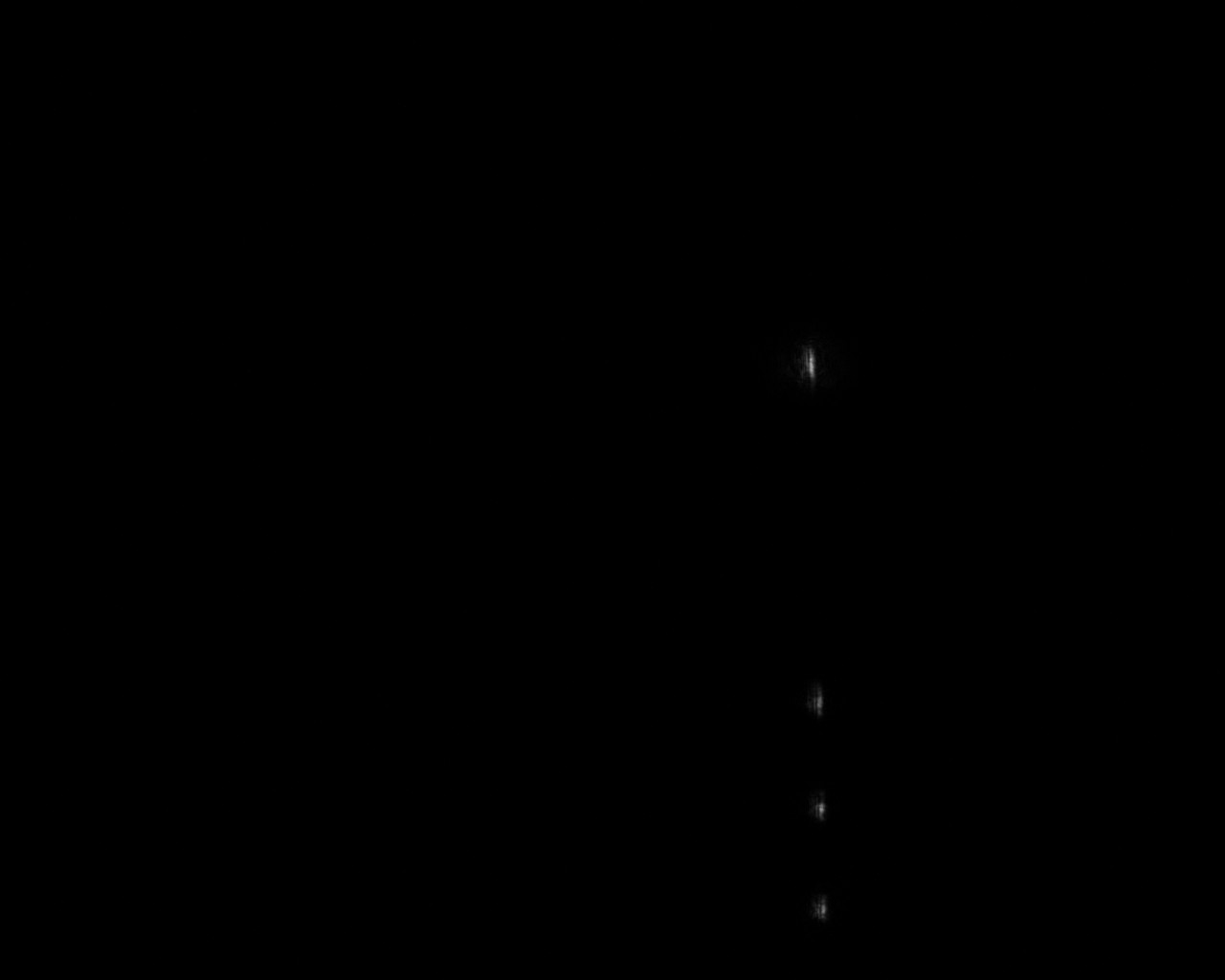
Below is what I hoped to measure; a nice series of dots.... The most upper dot originates from edge detection. This picture was made of a single facet.![]() The following picture was taken for multiple facets over a longer time. I believe to think I can see four facets. I can see two lines and two facets on that line. As you can see from above there are no longer 3 dots but 6 dots in a line.
The following picture was taken for multiple facets over a longer time. I believe to think I can see four facets. I can see two lines and two facets on that line. As you can see from above there are no longer 3 dots but 6 dots in a line.![]()
-
New lasermodule
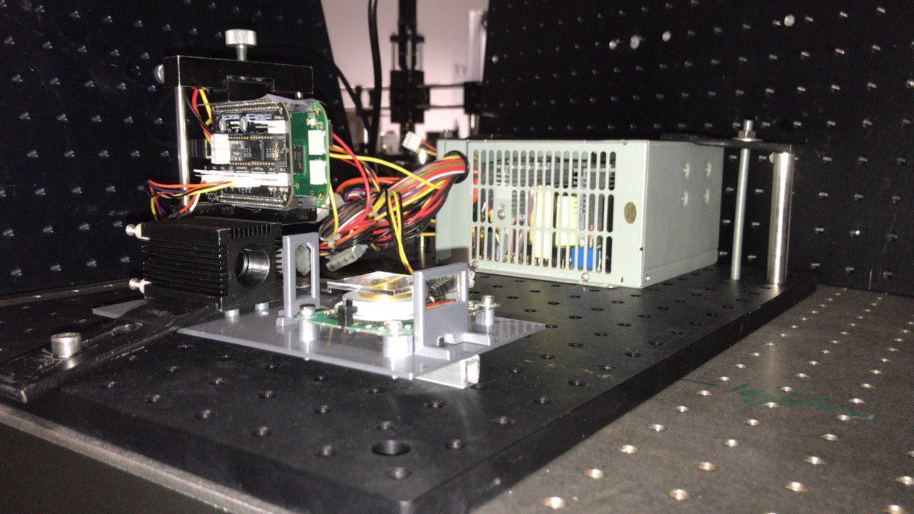
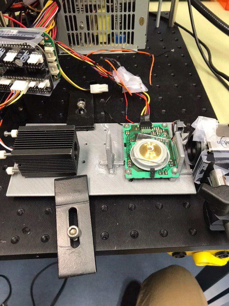
01/11/2019 at 18:16 • 0 commentsI have finished the new module. It can be mounted on the FELIX frame. Th laser is aligned with the prism, and both apsheric lenses. A photodiode has been added. The spotsize is still in the order of 25 microns and the cross scan error in the order of 40 microns. I still need to measure the jitter.
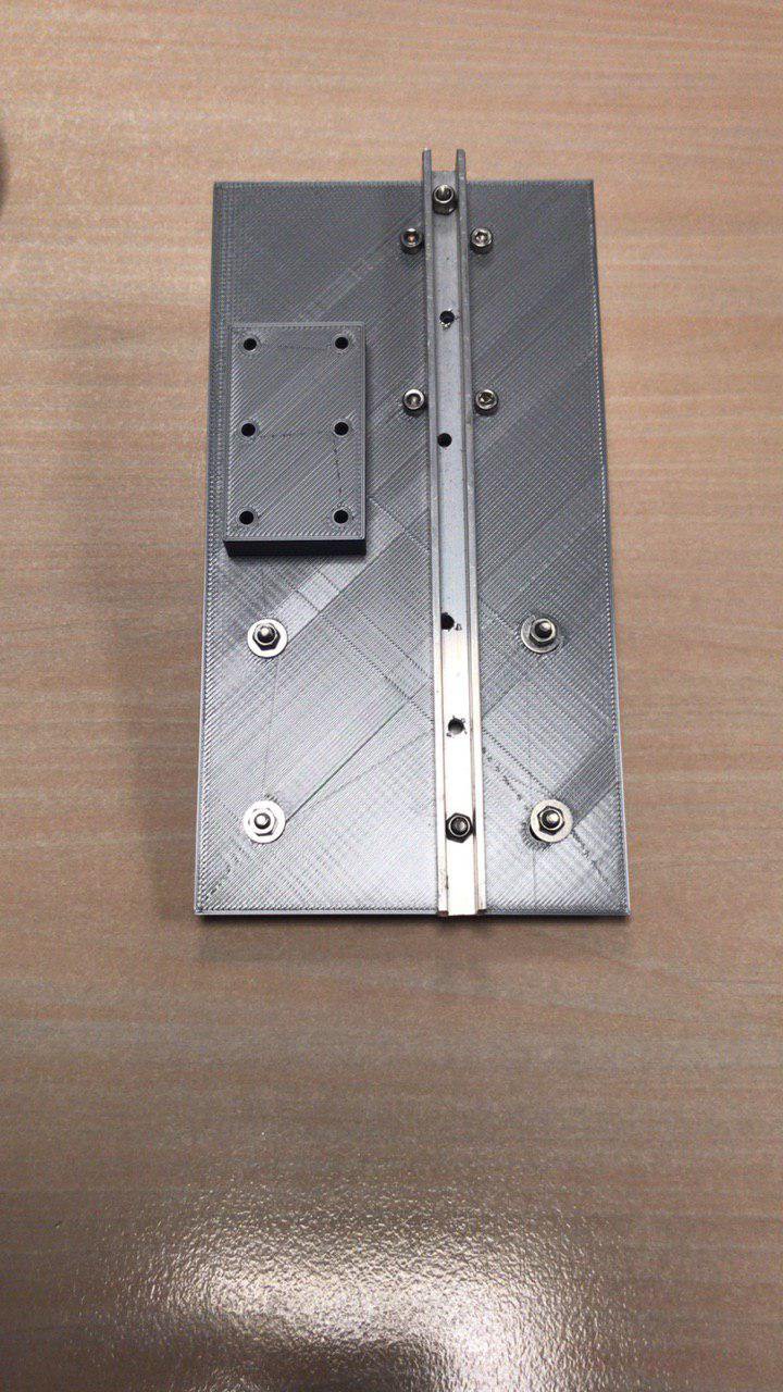
Aluminum bar has been added for reinforcement and flatten the plate. It was slightly curved (in the order of a couple of 100 micron). The laser and prism were aligned using shims. Used Loctite 222 to lock the washers, loctite 406 anaeroob glue to lock plastic part and UV glue to mount the plastics. The lenses were glued with CAF3 (silicon glue) to the plastic posts. I didn't do this very clean so the optics became slightly dirty. I used pre-wetted polyester wipers and cleantips swaps with ethanol to fix it. The aluminum u-bar had a height and width of 10 mm and a thickness of 2 mm.![]()
![]()
-
Position Photodiode
01/04/2019 at 11:06 • 0 commentsToday, I talked with my colleagues on the position of the photo-diode. In short, measuring the reflection is a bad idea as opposing planes in practice are not planar due to fabrication errors. I would therefore not correct for the jitter. The idea now is to add a prism or mirror and deflect the laserdiode beam upwards before it refracts through the lens or after it refracts through the lens.
This prism or mirror is imaged to be small, e.g. a cube of 5x5x5 mm. The light is hereafter measured by a photodiode. This measurement would account for the aberration. In my initial design, I used a mirror. The disadvantage is that it is harder to mount at an angle of 45 degrees. The prism has the 45 degree angle build in.
 Hexastorm
 The properties of a parabolic mirror are shown below;
 The optical system will produce a better spot quality than their previous galvo design without f-theta lens.
 Full overview of sample shown above, taken with smart phone.
 The following picture was taken for multiple facets over a longer time. I believe to think I can see four facets. I can see two lines and two facets on that line. As you can see from above there are no longer 3 dots but 6 dots in a line.