-
Closing the Security Gap
09/28/2014 at 15:33 • 0 commentsHTTP(S) and Websockets Security
There are a lot of open source home automation attempts out there. Many are missing some essential security that leaves them vulnerable. Those that actually allow the user to control physical things in their home are especially vulnerable. An attacker could gain control and cause an appliance to turn on-off repeatedly causing a hazard, could gain access to the home by opening a garage or door, or could just watch for human activity for other evil purposes.
I knew that getting ahead of the crowd meant imposing some strict requirements including physical and virtual security to restrict access only to those authorized and minimize the chance of an attack.
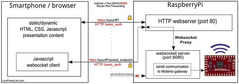
Sure, anyone can add some authentication, not a big deal. And it's not too hard to add SSL. I had thrown web sockets in the mix for real time updates (cf polling as a method of "updating" on end clients). So web sockets had to be secured as well. Since the node.js websocket server runs on a different port than the webserver, rather than securing two channels of communication (webserver and websockets) I implemented what I believe is the first OSHW home automation interface with real realtime two-way communication between the webserver and the clients, by marshalling the websockets through the webserver itself, and thus obfuscating the internal websocket port. Hence both the webserver and websockets traffic run on the same SSL port 433. The websocket server is obscured and any non localhost requests to it are blocked. The details of this implementation are extensively documented in this article on my blog. HTTP-Auth authentication blocks any intruders from accessing the web interface. Below is a diagram of this whole scheme.
![]()
Wireless Security
Another important aspect of security is obfuscating the wireless requests and making it harder or impossible to decode. This is achieved with hardware AES128 encryption on the wireless transceivers such that any wireless packets to and from the end nodes cannot be decrypted by an attacker.
A more sophisticated attacker armed with a $20 RTL-SDR dongle and laptop could listen for more extended periods of time and record messages and then replay them in hope to cause a door to open for instance. Such a simple portable SDR solution (cf. portableSDR project) is elegantly explained by w2aew in this video:
Hence the remaining gap to fill is implementing an algorithm to thwart any replay attacks for those critical commands that control physical things like appliances, lights, garage, doors, etc. This is essentially a way to salt each wireless packet with a sliding window type signature such that if it's replayed it would be obsolete. Until this is implemented, one can tune their end node transceivers output power to only be powerful enough to reach the home gateway, which would be recommended anyway to avoid polluting the RF traffic in your neighborhood. So unless you have a curious close-by neighbor with radio knowledge who might eaves drop on your RF traffic, it would make it harder for an external intruder to get physically close to your home/location to record your traffic and try to mess with it via replay attacks.
Rolling code vulnerabilities
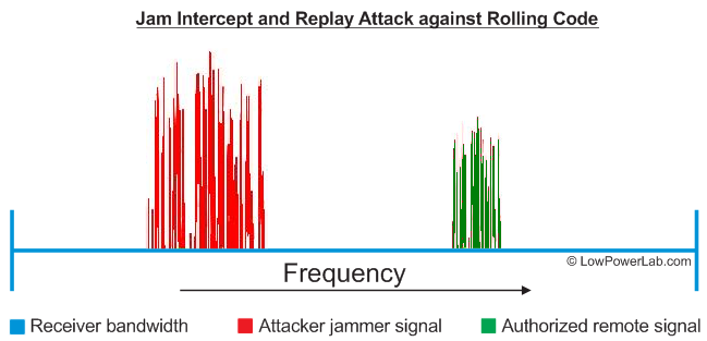
It seems a lot of key fob entry systems like auto locks and garage openers are using rolling code to secure their wireless communication. The transmitter increments a number in the packet with each subsequent transmission. The receiver remembers the last received token and knows what token or series of tokens are expected next. This attack involves blocking/jamming legitimate signal, then replaying the intercepted legitimate signal. Because of the jam, the receiver never receives the legitimate signal with the expected new token and thus the replayed message will appear legitimate.
![]()
I found this article that explains very elegantly how this all works and how the author was able to attack an auto lock using this method, via an inexpensive RTL-SDR device. Moreover, such devices as garage openers and perhaps key fob home door locks work this way. Scary.
To fix this we need to implement something that will require the receiver to be involved in each exchange. In SSL the receiver gives the sender a public key that can only be used to encrypt the message. Then the receiver uses a private key to decrypt that message. So in our case the messages are already AES128 encrypted so the messages contents are not readable to the attacker. We could then ask the receiver for a transactional token, a one time unique set of pseudorandom bytes generated by the receiver that will be used to "salt" the sender message. This technique will ensure the sender will send a different looking message every time *and also* that the receiver knows exactly what the unique expected token is. The attacker cannot spoof the token since they don't know the secret shared AES128 encryption key. One essential assumption is that the sender message will contain the security token in addition to the actual message. The encryption will ensure that 2 messages with the same content but with different security tokens will look completely different as far as modulated RF output.Since both receiver and sender are involved in each exchange, the receiver should expect the sender to respond very quickly with the encrypted and salted message. A short message takes a few ms to send at 55.5kbps for instance which is the default at the time of writing for the RFM69 library. Now even if an attacker records and replays messages, they are obsolete by the time they are received.
-
Architecture decisions
09/19/2014 at 03:58 • 0 commentsMy vision for Moteino Framework was to create an affordable/open/ideal/easy hardware platform that would fuel a new generation of wireless internet-of-things, and I think it came out pretty decent. My Hackaday Prize entry even made it in the top 50 semifinalists (out of 800+). More devices are being added to the Moteino Framework and existing ones are being improved to make it fun for those makers who like to DIY and solder their internet-of-things from easy to assemble kits. The end users have maximum freedom as far as using/building stuff with Moteino. They can build absoltely everything from scratch, as some have done, but some prefer to just save time and buy building blocks. Hence I funded my way through this adventure by selling ready made Moteinos and kits in my online webshop.
People have asked many times why the Moteino was designed the way it was, and why not use this and that and the other type of MCU, transceiver type, radio band, or wireless technology. The number one reason why Moteinos are what they are today is because in the end they need to be designed to manufacture, work well, be reliable, license free, easy and fun to use in a friendly board format, cheap to buy or make, achieve long open air range or excellent indoor obstacle penetration when used with transceivers, etc. Here is my reasoning behind all these decisions and the answers to some frequently asked questions.
MCU choice – Why not ATTiny/ARM chips? They are cheaper!
Because it makes little sense, economically and practically, for what I had in mind. ATtinys are very memory challenged (typically FLASH not more than 8KB and SRAM not more than 512b), are somewhat supported in the Arduino IDE with some tweaks, don’t generally have real dedicated SPI/i2c/serial hardware support (some have SPI or serial). The bootloaders typically take a big chunk of the already limited FLASH. They cost less than an ATMega328 but the savings would never justify the features tradeoff unless for projects where all you need is a few I/O and you program it once and never have to touch it again. In fact some of the “larger” ATTinys are getting close in price to the popular ATMega328. ARM is a steep learning curve, the chains are not very easy to get going and the large fine pitch SMD chips are harder to get started with unless you get ready made development boards. Tools are also costly and the general public has an easier time with Arduino/AVR.
Could be much smaller with ATTiny or with other board layouts/set of hardware
Really? I could shrink the Moteino to the size of a fingernail (I actually did a project where the diameter of the circular board was 10mm with a QFN-28 ATMega328 on it, no kidding, the ICSP was on a header that would snap off after programming, leaving the circular 10mm finished board). You can do almost anything you can put your mind to. The big question is are they designed for manufacturability? Are they easy to use to the average electronic hobbyist as well as for the experienced maker? Are they a building block for greater things or are they a stumbling block? I am personally willing to invest a few bucks more to get the luxury of a tool that is not a pain to get started with and just works.Why not CC1101 / NRF24L01 / other cheap ebay transmitters?
![NRF2]()
I really wanted to like these and I’ve done my own open air range testing with these NRF radios before I moved on to settling on RFM69. They are simply hopeless in terms of range. They have higher power versions (the PA+LNA) but those are hopeless in terms of size and power consumption and cost several times more than a RFM69. Most versions I’ve seen have a 2×4 header that was a challenge to fit flat/tight anywhere.
Why not use “inexpensive off the shelf” transmitter and receiver pairs? After all, they are just $1 on ebay!
![transmitter]()
Wow, I’m not impressed. They are inexpensive and you get what you pay for, a leg or an arm. I want a full set. You can use these but you will be sorry the first time you build a project where you want to get an ACK back from a node, ie need both transmit and receive (transceiving). Or transmit through an extra wall or from across the street. They have no hardware packet engine, encryption or CRC or anything close to what I want in terms of features. Sure you can do all that in software but I’d rather code my new sensors and ideas than spend my energy on reinventing the wheel only to save a few bucks. Also I don’t consider ebay a reliable stream of component sourcing.
How about Xbee/Zigbee?
Not much to say here except my very first experiments were with XBees which were about half the range of RFM12B and about 4X the price and power consumption was not nearly ideal. Quickly became obvious this is not the way to go.
![]() Fun fact: on the side is a user submitted photo in which he is testing a Moteino+RFM69 with tweaked RFM69 Lib settings for low bitrate/bandwidth and tweaked antenna to achieve an impressive 1.75Km range. This is fantastic and it means Moteinos are great for long range telemetry where bluetooth, wifi and other alternative technologies would be impossible to use and cost prohibitive. When I get stories like these about my product this makes my day. The full story and details are in my blog forum.
Fun fact: on the side is a user submitted photo in which he is testing a Moteino+RFM69 with tweaked RFM69 Lib settings for low bitrate/bandwidth and tweaked antenna to achieve an impressive 1.75Km range. This is fantastic and it means Moteinos are great for long range telemetry where bluetooth, wifi and other alternative technologies would be impossible to use and cost prohibitive. When I get stories like these about my product this makes my day. The full story and details are in my blog forum.The choice of RFM69
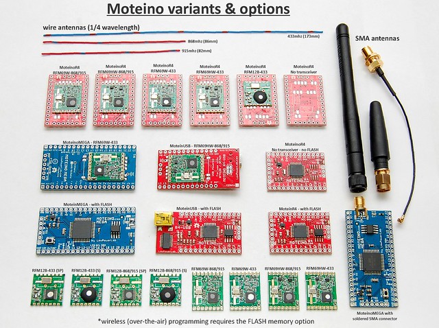
So I’ve gone from RFM12B (which is still supported on all Moteinos) to RFM69 (W and HW). The reasons are many, and it worked out as a great trasceiver, affordable, and the RFM69 library I’ve created for it has become very widely used. Meshing is also possible for special applications. But in most cases meshing is not needed because by tweaking the settings, ranges of over a mile is achievable. The out of box RFM69 lib settings will give you several hundred meters in open air and should easily cover a 1 acre typical residential property/home. By contrast RFM12B could barely get from one end to the other in my home, with dead spots and dropped packets, unless I seriously decreased the bitrate. It’s also the right size, fits perfectly on the belly of all Moteinos and is the right price. The end product is a very compact node that can fit in almost anything, can be easily powered from a range of sources, and doesn’t require twisty weird assembly and microscopical soldering to bring it to life.
![]()
Design for manufacture - IS YOUR PROJECT "PRODUCTIZABLE" ?
![]() This is very important if anything you make is ever meant to scale. I see a lot of projects that are cool, but have more of an artisan feel to them, which is perfectly fine, but in terms of making 100 or 1000 of them, it would require a small army of people or countless hours to solder and custom fit/bend/twist/test. I hope the THP judges will see these issues and take them into account when judging between the good and great THP semifinalists based on this consideration.
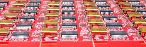
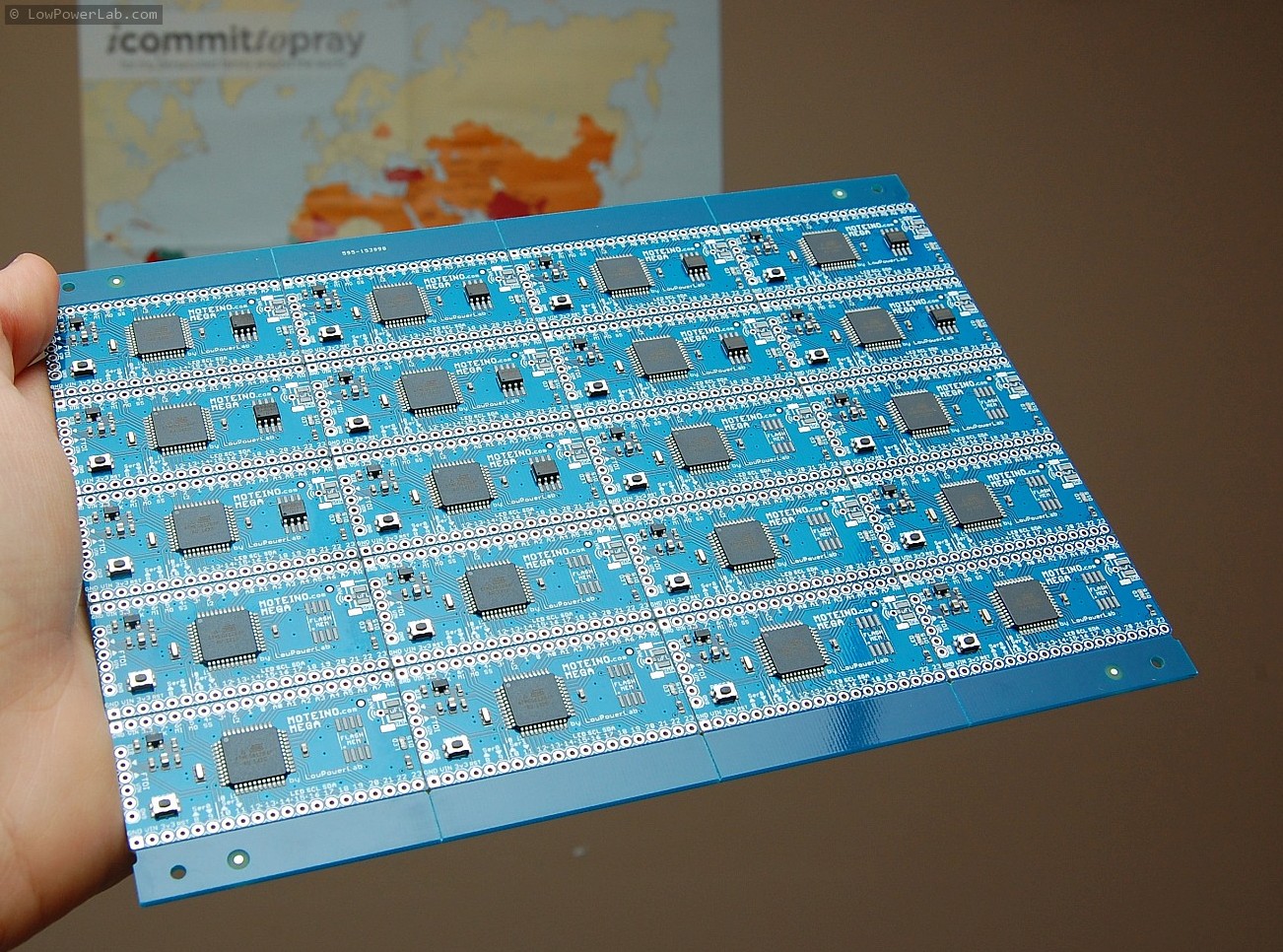
This is very important if anything you make is ever meant to scale. I see a lot of projects that are cool, but have more of an artisan feel to them, which is perfectly fine, but in terms of making 100 or 1000 of them, it would require a small army of people or countless hours to solder and custom fit/bend/twist/test. I hope the THP judges will see these issues and take them into account when judging between the good and great THP semifinalists based on this consideration. ![]() PCB making is affordable and anybody can do it with all the open/free PCB layout programs out there, but once you move from individual boards to panelized designs that need to be assembled into a pick and place it’s a whole different story, and a lot more things come into play. EEVBlog and others have done a good job explaining some of the challenges of designing for manufacture. This factor alone will make the difference between a good or bad design in the long run. With Moteino I tried to think of manufacturability from the start. I knew if my design was bad it would never get past a revision or two and nobody would want it. If it was good then I would eventually end up requiring machine assembly and rapid testing. Currently all Moteinos are assembled on my new real pick and place and reflowed in a real reflow oven. Yes I believed in my vision so much I ended up buying a pick and place to make my projects (I was getting tired of doing it manually too). Then they are bootloaded and tested manually using a jig I made for them similar to this. It goes very fast but it was a long journey to get here, nevertheless quite rewarding and fulfilling one. Here's some eye candy:
PCB making is affordable and anybody can do it with all the open/free PCB layout programs out there, but once you move from individual boards to panelized designs that need to be assembled into a pick and place it’s a whole different story, and a lot more things come into play. EEVBlog and others have done a good job explaining some of the challenges of designing for manufacture. This factor alone will make the difference between a good or bad design in the long run. With Moteino I tried to think of manufacturability from the start. I knew if my design was bad it would never get past a revision or two and nobody would want it. If it was good then I would eventually end up requiring machine assembly and rapid testing. Currently all Moteinos are assembled on my new real pick and place and reflowed in a real reflow oven. Yes I believed in my vision so much I ended up buying a pick and place to make my projects (I was getting tired of doing it manually too). Then they are bootloaded and tested manually using a jig I made for them similar to this. It goes very fast but it was a long journey to get here, nevertheless quite rewarding and fulfilling one. Here's some eye candy:![Got pick and place?]()
-
Pi gateway upgraded to battery backup
09/17/2014 at 21:18 • 0 commentsThe gateway that drives the Moteino Framework relies on power from the utility. If there is an outage, even a short one, the RaspberryPi will shutoff and SD card file system could be corrupted. So I upgraded the gateway from ATXRaspi to MightyBoost which supports the same nice shutoff button interface but adds the ability to switch to battery backup in case of an outage, and monitor the battery voltage in case power is out for a long time. The goal is to always shutoff the Pi gracefully to avoid SD corruption.
![]()
I had to lasercut a new mid layer for my existing Pi Gateway lasercut case. I have posted the changes (corel and DXF files) in the github repo so you can customize &/or lasercut your own if you’d like. As usual, I like to cut the new template in cardboard and do a fitting test, measure any adjustments, re-cut if needed, then finally when it’s perfect cut it in the more expensive translucent acrylic.
![]()
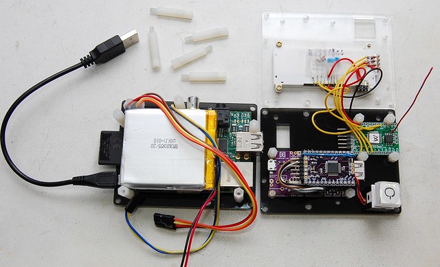
I have used one of my OSHPark prototypes and an old Moteino R1 to drive the MightyBoost using the provided sketch. This allows me to use a power button as before, monitor backup battery voltage through Moteino A7, control the standalone i2c LCD via Moteino to display status and messages from the Moteino Framework. And yes, there are 2 Moteinos in this setup. I could have used a single Moteino for everything, but that would mean combining the MightyBoost control sketch with my main RFM69 receiving sketch, and I wanted to avoid that.
![]()
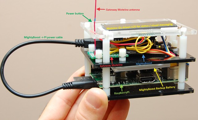
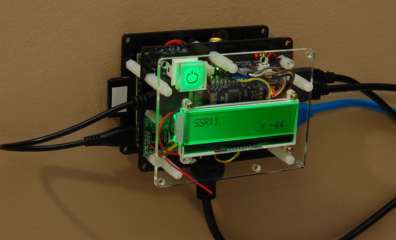
Also, the MightyBoost sketch will hardly ever need changes. But the gateway sketch is tweaked quite often, and I like to wirelessly program the gateway Moteino without loosing control of the MightyBoost power (ie a wireless programming sequence involves a hardware reset which would shut power off on the MightyBoost Moteino). I hope that makes sense. For an end user, in terms of cost, the extra transceiver-less Moteino that drives MightyBoost is a mere $12.95 at time of writing, hardly something to argue about as far as savings. I think it’s a good tradeoff for modularity and separation of concerns, and allows maximum flexibility. If changes are required on the MBoost Moteino, just power it off, plug in your FTDI, upload the sketch, then power back on. As simple as that. Here is the final install of this upgrade:
![]()
The full writeup is on my blog and the laser cut plans are on github along with source code for the gateway firmware. See the previous blog entry that goes into more detail about the laser cutting.
![]()
-
New MotionMote and OLED Moteino receiver
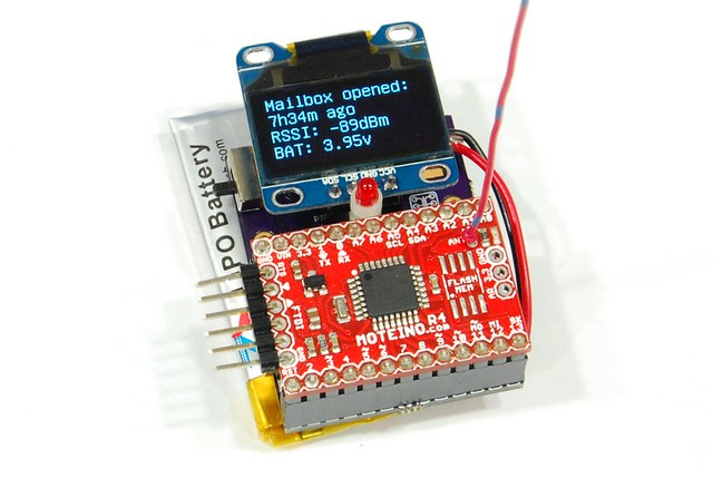
08/20/2014 at 19:36 • 0 commentsOver the past year and since I published my initial mailbox notifier project, I've been asked by various people if I could build a standalone receiver for the Moteino network of things. Some people wanted just an LED to light up when a certain packet is received (like the mailbox was opened), others wanted an LCD to see the entire message and battery level, or other things like that. I kept wanting to get to this, however I was always too busy but kept juggling the idea in my mind.
At the same time I wanted to have a better MotionMote solution (also featured on HAD). One that would be chargeable and programmable through USB. This could be used as mailbox notifier, or as motion detector.
So the past few weeks I've been working on revisions of a combination of the above: a motion detector and standalone Moteino receiver with LED and OLED screen. The result is below (I will need to make a nice case for the receiver):
![]()
This combined PCB can accept a standard PIR sensor, or a typical I2C
![]()
SSD1306 OLED screen to create dual functionality. It can be a motion detector (or mailbox notifier), or a receiver for the motion/mailbox message, or of course a receiver for any of your Moteino framework(s). Just charge and program it over USB. It will take a 1000mAh battery which should fit nicely under the PCB and into the lasercut acrylic case, and should provide many months of runtime as a motion sensor, and probably a day or two as an OLED receiver.
-
Solution for RaspberryPi battery backup
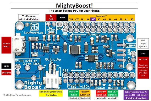
08/19/2014 at 02:04 • 0 commentsTo solve the battery backup issue I designed a board that would run like an ATXRaspi (when paired with a Moteino), but in addition also have backup power from a LiPo battery. It acts as a charger/5V booster and can provide up to 2A for 5V loads. This is perfect for the RaspberryPi computer running the Moteino Framework.
I was able to get past the prototype stage and get a batch of these MightyBoost boards assembled. Here is a diagram of the various functions/pins on the board:
![]()
It has many uses (like charging your phone, or just act as a standalone supply for other 5V embedded systems). But mainly I designed it to be used with things like the RaspberryPi, providing a power button interface for easy shutdowns, automatic switching to battery backup when power is lost (battery is also charged while plugged in externally), battery monitoring and clean shutdowns when the battery runs dry.
Here is the MightyBoost details page and more will be added later. I need to upgrade the gateway computer to a newer Pi and also upgrade from ATXRaspi to MightyBoost. Stay tuned for more updates.
-
More SwitchMotes Online!
08/14/2014 at 16:31 • 0 commentsI installed some more SwitchMotes and made some changes to add them to the web app. Now they can be controlled remotely from any internet location. Of course, when someone turns them ON/OFF that action gets updated on all the clients connected to the web app running on the RaspberryPi (via SSL sockets.io).
![]()
![]()
-
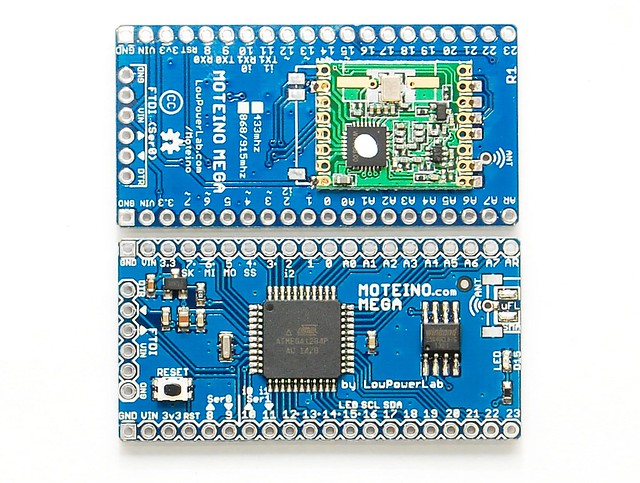
Added new MoteinoMEGA
08/14/2014 at 16:16 • 0 commentsAfter suggestions from some fellow makers and users on my blog, I released the new MoteinoMEGA along with all the source and details. This is based on the more resourceful Atmega1284P but otherwise has all the other loved features of the traditional Moteino. Wireless programming via DualOptiboot+FLASH, a lot more flash for sketches (128K), 8 times more RAM! (16K), another hardware UART/serial and a bunch more IO!
I have also improved some functionality of the RFM69 library to support it and address some issues. Also I made SPI transactions nonintrusive such that it would work with other SPI devices that don't run in MODE0 that the RFM69 and FLASH devices use.
- The release notes are here: http://lowpowerlab.com/blog/2014/08/09/moteinomega-available-now/
- The library changes notes are here: http://lowpowerlab.com/blog/2014/08/13/library-updates-mega-support/![MoteinoMEGA]()
Here is the diagram of the new MoteinoMEGA:
![MoteinoMEGA pinout diagram]()
The Moteino Framework
Automation framework based on wireless Moteino nodes.