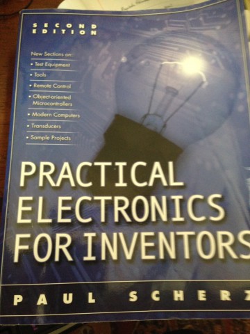
Yesterday and today I broke out my favorite electronic books to try and understand the diode capacitor relationship I built. Was my logic in use correct? Does it have a name? My guess is that this is a transient circuit since we have .."a sudden change in voltage introduced by an external agent...", aka Mr. Fly being electrocuted. Book has some formulas to model this behavior which I will look into once I have POC2 up and running.

I will map the complete circuit but this is what I understand.
1.) The diode does act in the way I intended, one way current/voltage flow. Learned it has a -0.6V drop when in series like I placed it. Since I might be tapping off the transformer it could act as a 1/2 wave rectifier as well.

2.) The electrolytic capacitor that is inline with the diode does charge like I expected. The closest thing I could find is it is a capacitor under forced response.
3.) The ceramic just helps even things out a little, bypass circuit to get rid of some undesired ripple. Also drains the electrolytic cap. since the ceramic is connect to ground.
NEW IDEA--> Maybe putting a resistor in parallel with the ceramic will help the electrolytic drain faster and give a snappier recharge picture. Also may add a resistor before the diode to get the voltage < 1.1 so I can switch the Arduino ADC over to 1.1 reference instead of 5V reference. Since I have been testing with a piece of wire I have a feeling a fly will not pull as much a load as my test wire. I could be wrong since a short is a short and as long as the short does not break then we should have the same results.
 BDM
BDM
Discussions
Become a Hackaday.io Member
Create an account to leave a comment. Already have an account? Log In.