 Jorj Bauer
Day 2's fun ended with an odd counter problem - where the carry from the low 4-bits of the program counter is being applied to the high 4-bits one clock cycle too early. As fun as it is to count "14, 15, 31, 17, 18" I'd much rather that my computer counter "14, 15, 16, 17, 18" like all the other computers. So my task for today, then, is to delay the application of that carry bit by one clock cycle.
The DM7474N is a dual D-type flip-flop. It's easy to use a D flip flop as a 1-bit, 1-cycle delay. (I had indeed forgotten that the 'D' stands for "Delay", even. Thanks Google.) But instead of that, here I grabbed a DM7476N dual J/K flip-flop, and convinced myself that I remembered how to use one as a delay instead of a D-type.
 After about a half hour of confusing the hell outta myself, I went back to the obvious choice and built it out of a 7474. :)
Now the counting logic looks like this, with the flip-flop delaying that low carry by one clock cycle:
| High bits | D Flip-Flop out ("Q") | D Flip-Flop in | Low Carry | Low bits | Output |
| 0000 | 0 | 0 | 0 | 1000 | 8 |
| 0000 | 0 | 0 | 0 | 1001 | 9 |
| 0000 | 0 | 0 | 0 | 1010 | 10 |
| 0000 | 0 | 0 | 0 | 1011 | 11 |
| 0000 | 0 | 0 | 0 | 1100 | 12 |
| 0000 | 0 | 0 | 0 | 1101 | 13 |
| 0000 | 0 | 0 | 0 | 1110 | 14 |
| 0000 | 0 | 1 | 1 | 1111 | 15 |
| 0001 | 1 | 0 | 0 | 0000 | 16 |
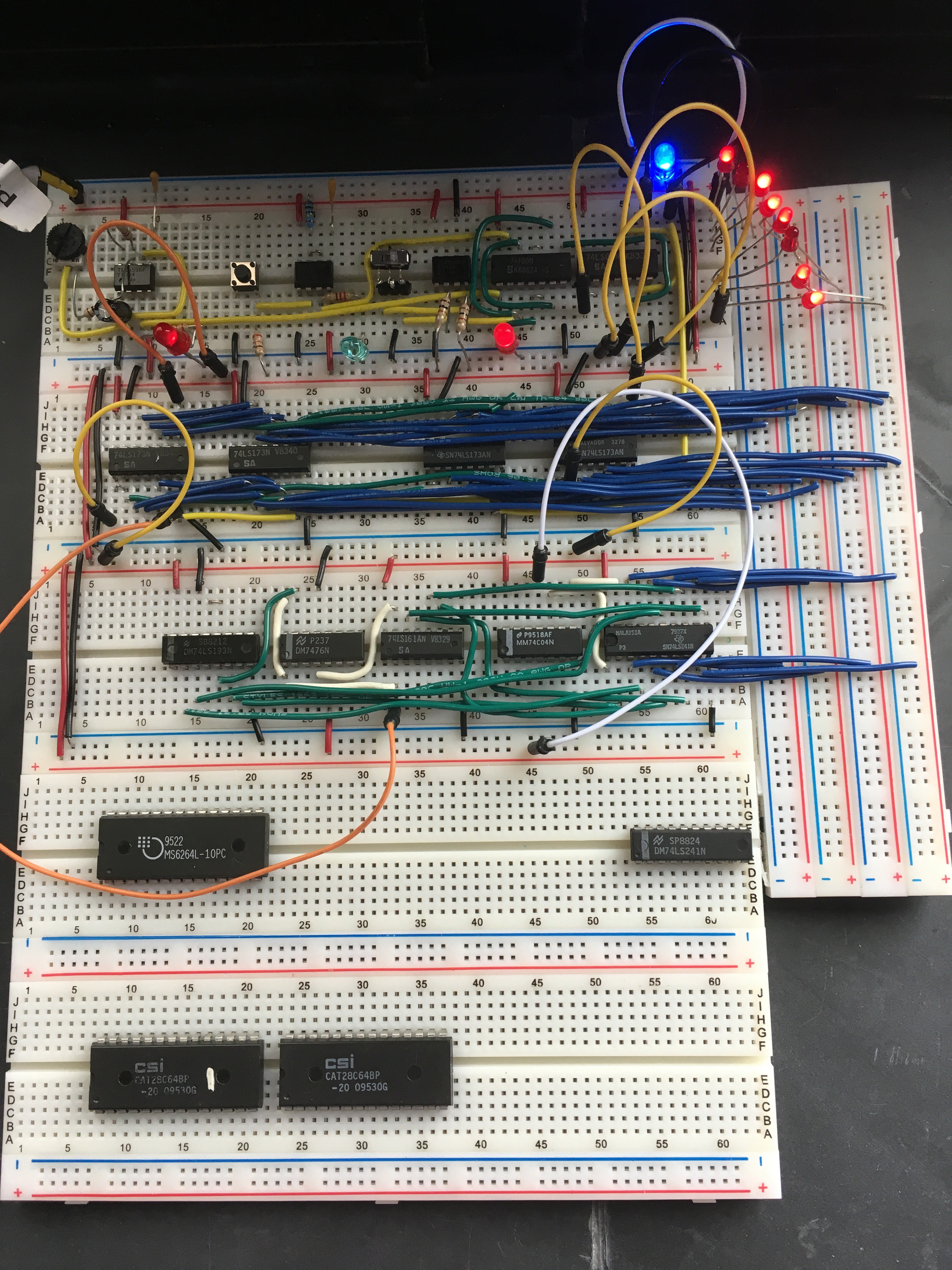
But there are *two* new ICs in the clock module. What's the other one?
I played for a little while with reversing the two ICs - using the '193 as the low bits. Immediately there's a problem, because the carry out from the '193 is active-low. So I needed an inverter while playing with that configuration. The MM74C04N from my pile of parts did just fine.
I've also connected the output of the full 8-bit program counter to the bus using one '241, which is seemingly designed as a bidirectional 4-bit bus interface (not a unidirectional 8-bit bus interface). The two separate enable lines on the '241 have opposite control logic: one requires a low signal to enable, and the other requires a high signal. If you were using this as a bidirecitonal 4-bit control, you could tie together the two; if the logic were high, you'd be flowing in one direction across the chip and when you switched to low, you'd be going the other way.
Since that's not what I'm doing - I only care to gate the output, tri-stating *to* the bus, not worrying about what comes *from* the bus just yet - I should probably tie those two together to one control line via an inverter. So it's wired to the hex inverter '04; when one line is low, the other is high, and I can turn this on and off as a single unidirectional 8-bit switch with just one control line.
Discussions
Become a Hackaday.io Member
Create an account to leave a comment. Already have an account? Log In.