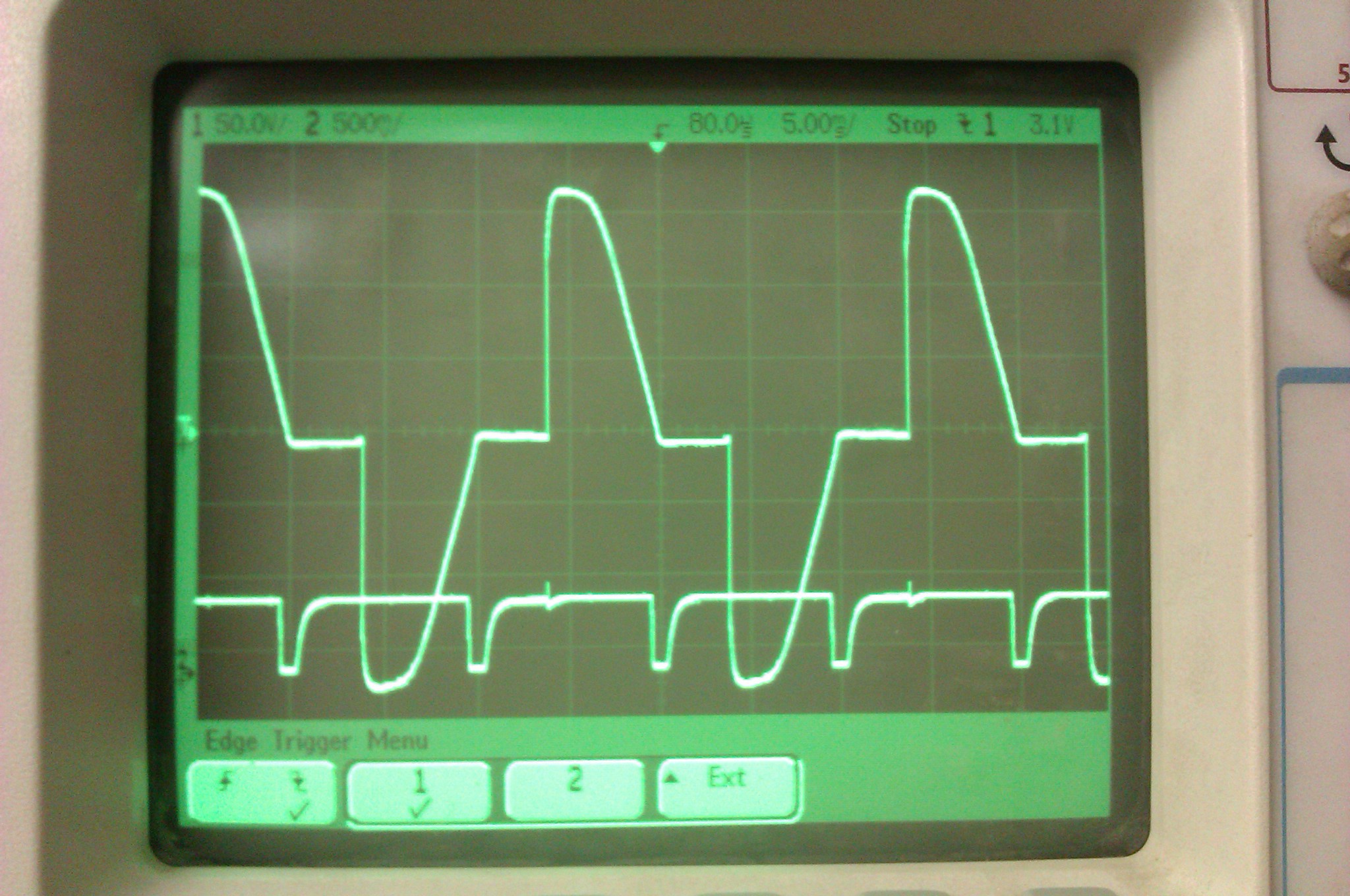
The next step was to test the phase control. Now I had functioning ZC detector and a working TRIAC I hooked up a pot on an analogue input and got hacking on the software.
This was pretty straight forward as I'd done some work with timers and PWM on Atmels before. It's a bit different if you've only done "Arduino" stuff before though, as it's necessary to twiddle some bits in some registers - which can look a bit scary.
Take a look at lines 55 to 61 on the arduino sketch. First we clear all the control registers, so the timer goes to default settings. Then by putting values into TCCR2B we set a prescalar to slow the counter down 1024 times (I looked this up in the datasheet).
Finally I enable the overflow interrupt by writing a 1 to the correct slot in TIMSK2. Look at the interrupt handler called ISR(TIMER2_OVF_vect). This gets run everytime the timer overflows.
Now we have a setup where timer 2 will count up from 0 to 255 (as timer2 is a 8 bit counter). This will take 0.016 seconds, but if we start the counter at around 150 it will only take 0.01 seconds, or half a sine wave on the mains frequency of 50hz. So by varying the starting point of the counter between 0 and 150, I can generate a trigger for the TRIAC that will be set it to be turned on for longer or shorter times. I mapped the analogue input from the pot to the range of 0 to 150 on the timer's register.
In hindsight, I should have used timer2 for the rpm counting and timer1 for the triac control, as I'm wasting
The next step is to sync the timer to the mains frequency, which is what the zero crosser circuit does. I made an interrupt handler called ZC_INT(), which just turns off the TRIAC and sets the timer2 count register to our desired starting point.
This nearly all worked first time, but there were a couple of issues that stopped it working perfectly.
- I was detecting a rising edge on the ZC interrupt, which happens just after the zero cross. This stopped the TRIAC from turning off cleanly at some values.
- There was some noise when the TRIAC turned on, on the ZC interrupt (still slightly visible on the scope trace below), which was causing double triggering. I fixed this with a low value capacitor between ground and the signal.

 matt venn
Discussions
Become a Hackaday.io Member
Create an account to leave a comment. Already have an account? Log In.