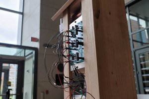
This board is part of Fyber Labs Flex Module project.
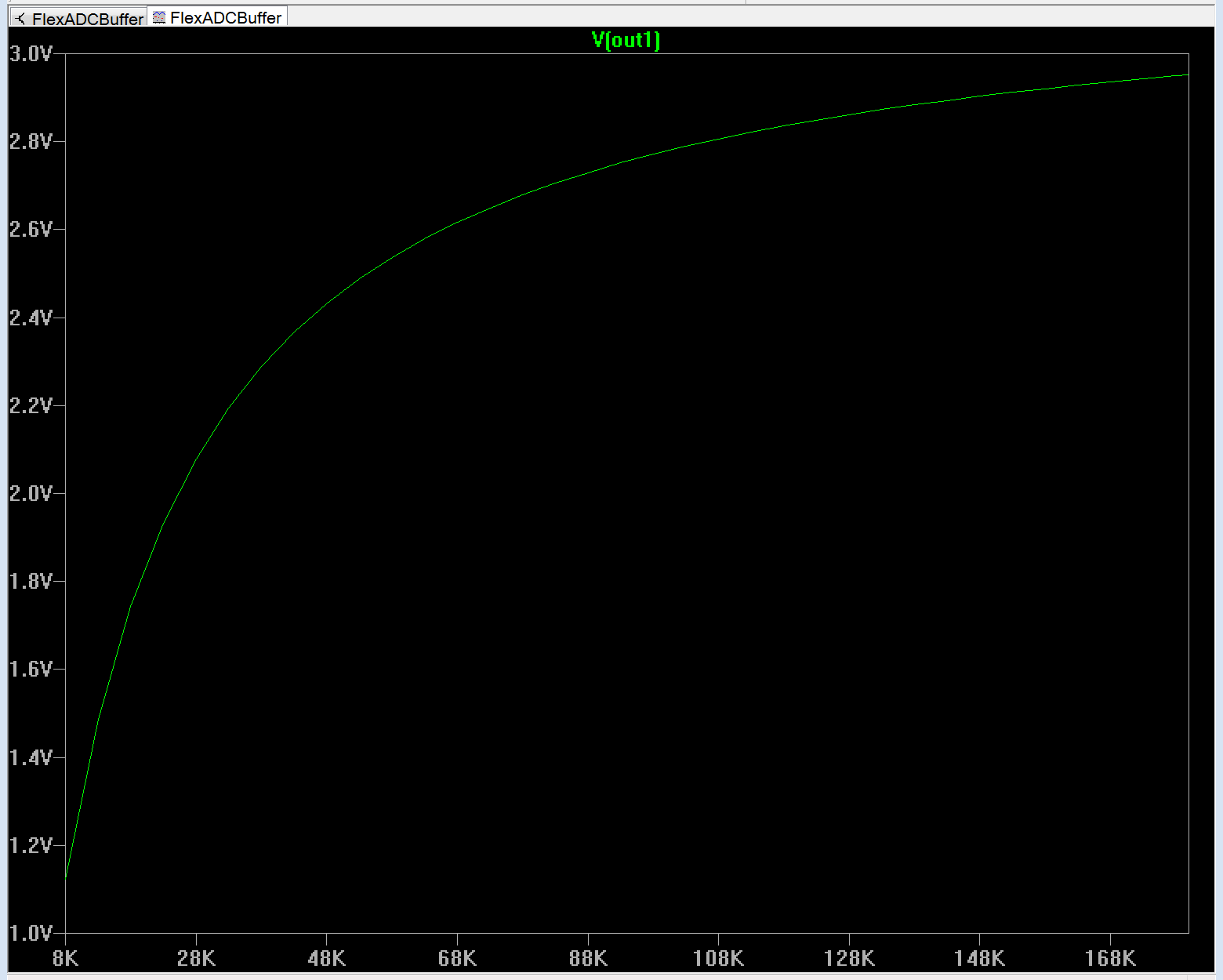
Flex sensor input to ADC will be essentially DC voltage so filtering isn't critical. The buffer provides uniform impedance and somewhat linear use of the 0-3.3V ADC input for the resistance range of the sensor.
Sample 4.5" and 2.2" flex sensors required significant break-in. Resistance varies depending on amount of break-in and will likely increase with age/use until failure.
2.2" sample flex break in (2 minutes of ~1/4" circumference bend hand rolled through flex sensor).
| Sample1 | Sample2 | Sample3 | Sample4 | |
| Initial | 33-33-45 | 20-20-39 | 29-29-34.5 | 31-31-44 |
| During | 28-35-60 | 31-36-77 | 31-42-79 | 32-75-115 |
| After | 40-120-180 | 40-118-150 | 44-88-140 | 39-88-150 |
Resistance in KOhm (reverse bend, relaxed, forward bend)
So 2.2" range is around 20-150KOhm. 4.5" is 8-90KOhm.
LTSpice simulations were stepped through a sensor resistance range of 8K-180KOhm showing the response for these channels utilizing a ST TSX561 op-amp and 150KOhm/0.1uF pairs for a fc=10Hz,Q=0.5 Sallen-Key LPF variation.
Any software related will be released under BSD or MIT license. SAAS or cloud based software will be AGPL.
 Chris Hamilton
 oneohm
 Markus Leutwyler
 kamalkedin123
 Keerat Singh