There were a few basic thoughts I had in mind when working on the wireless interface, ideally the clock would;
- control the ramp on of the lighting for the dawn simulation
- have the ability to turn the lights off if the snooze button was pressed
- maintain all the functionality of the Lutron PICO remote, and have it easily accessible
At this point I had it in my head that I needed to reverse engineer the PICO wireless remote protocol so I could incorporate the design directly into my clock. Thus began my trip into the rabbit hole which I later abandoned once I re-evaluated my approach. But none the less let me fill you in on where I went and where I left off, so if anyone has further info to help assist in understanding the transmission packets I would greatly appreciate it.
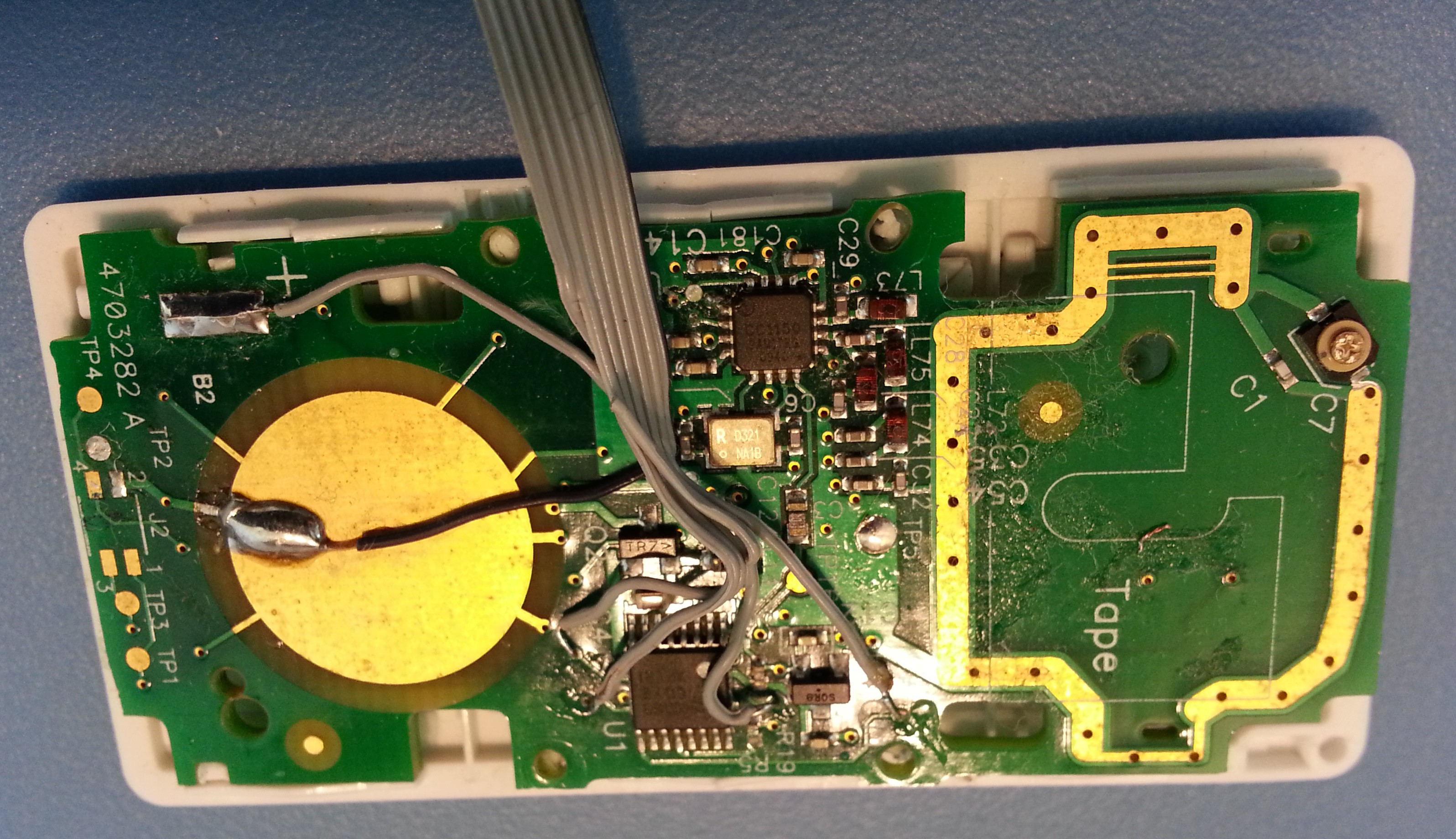
I first identified the main IC's on the PICO remote, noting the TI CC1150 as the chip responsible for the wireless transmission. Armed with the data sheet and a Saleae Logic analyzer I soldered on some 30AWG wire onto the SPI pins and started recording some data.
 (This image actually shows connections to the power and buttons but the idea is the same, I had already de-soldered my SPI connections and wasn't about to re-solder to take a picture of it :)
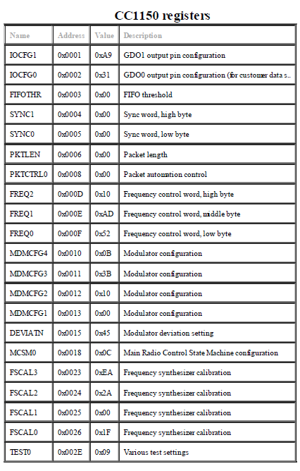
Using the SPI analyzer in the Logic software, I exported the data to a CSV file to pick apart further (see WirelessAnalysis folder in github for the Logic captures and a spreadsheet for both on and off command data). The first packet in the transmission resets the transmitter and re-establishes all the control registers. Registers are set as follows;

Using TI's SmartRF Studio 7 (a free download) I entered the above values into the registers which then provided the below configuration (which could also be deduced from the data sheet register explanations, but this seemed quicker);
Base Frequency 433.602844 MHz
Channel Number 0
Channel Spacing 49.987793 kHz
Xtal Freq 26 MHz
Data Rate 62.4847 kBaud
Modulation Format GFSK
One of the oddities of the transmission packet, is that it alters the FREQ0-FREQ2 registers twice but with slightly different values. It is not immediately apparent why this would be done . . . I plan on re-visiting this at some point in the future.
The data packets:
Feeling fairly confident in what I had found so far I continued to evaluate the data packets that were repeated after the initialization packet. It was determined that the quantity of repeated data packets was based on the length the user pressed the button, although I'm sure there is a minimum repetition that occurs regardless of how fast you can press a button. Each data packet remains the same length and carry's all the same data with the exception of the pulse count byte and what appears to be a CRC and checksum value (highlighted in red in the PICO.xls file in github). I've got some research to do here to see how these values are actually calculated.
The pulse counting byte always begins at 0x01, and then increments as follows; 0xC1, 0x61, 0x91, 0x31, 0xF1, 0x49, etc. Noticing a pattern, I realized that if I mirror the binary of each number, add three, and mirror again I follow the pattern above. So for example 0x91 in binary is 1001 0001, then mirrored as 1000 1001, plus three, 1000 1100 and mirrored again 0011 0001 equals 0x31 which is the next number expected in the count. I'm not clear on whether the pattern works this way due to the transmission system, i.e. FIFO (first in, first out), so it may look funny on the transmitter side, but make perfect sense on the receiving side. . . once again something I'd like to revisit to understand better.
The actual command data is done in two bytes (highlighted in yellow in the PICO.xls file in github), and appears to always add to the same value, for example ON has the values 0x74 and 0x12, while OFF has the command values 0x76 and 0x10 which I assume is some type of parity system going on, as one is incrementing and the other de-incrementing by the same amount.
Other bytes in the packet structure include a preamble and a seven byte unique device ID according to one of the PICO patents I searched through. However not having a second PICO remote to test, I'm not sure which bytes are the ID. I also read that the packet length was 72 bits, which seems inconsistent with what appears to be going out.
Time to regroup:
After getting this far, I figured even if I didn't understand all the code, I had all the data required to copy into my system and just spit the data back out as I had recorded it, after all I had all the SPI instructions layed out from the Logic. This is when I briefly looked at antenna theory and finally realized I was wasting too much time trying to recreate a remote I already had functioning. I decided to put this puzzle to the side and continue working on the clock using the existing remote.
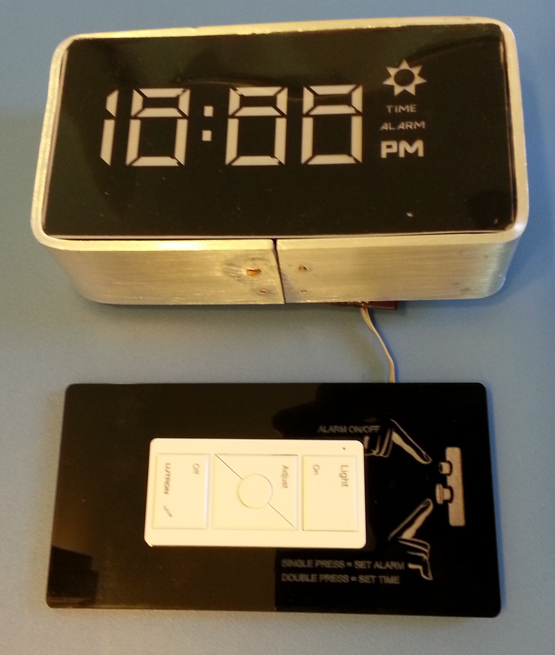
Well that was a long read just to say I cheated and soldered some ribbon cable to the remote. 30AWG seems to be a perfect fit into the PCB's via's, one wire per button that I planned on using and then a wire for power and ground, as seen at the top of this log. The remote is now powered by the 3.3V system rail, and the buttons are pulled to ground to simulate a press. This meets the three basic requirements I had set out to achieve.
The acrylic back plate was cut to fit the remote and will be secured with the Decora insert support that Lutron sells. Having the remote remain functional and in a given location works great for when your in bed, as you can just reach over and adjust the lights as needed. As I am familiar with the clock layout, it is easy to reach behind and turn on/off the lights without needing the flip the clock around to actually see the remote.

Before I wrap this portion of the log up, I would just like to say that even though I was off on what ultimately was a tangent to the main project, it was worth all the effort as I learned a ton along the way. I still plan on revisiting this just because I'm stubborn like that.
Discussions
Become a Hackaday.io Member
Create an account to leave a comment. Already have an account? Log In.
Andrew, glad to see someone else is looking at this. Its pretty much my lowest priority project. I tend to work with my captures while flying on airplanes, which has obviously not happened much this year!
Anyhow, maybe we should setup a dropbox or something to share data. I too have a hackrf, and my goal is to take over the lutron bridge so everything will go through ***MY*** server, not lutrons :) Then it can never be turned into bricks!
The reason I say we should share data is that I do not see a constant 1-0 every 10 bits. Maybe I'll try to post a pic to imgur to show what I see...I have a "tool" (really a crappy windows program I'm writing because I didn't have QT installed when I started....and I'm ashamed to say, I still don't! but I digress....I'm keeping the GUI code seperate, and my various filters seperate so it should eventually be able to be released as a nice binary work tool....but I'll see if I can post a pic of some data I have where I'm adding a dimmer switch to the bridge...
you can send me a direct message on here. Heck, I think this project has abandoned the idea of reverse engineering the lutron protocol, so maybe we should start our own page!
Edit - You'll have to pardon the bit errors, and the occasional extra bit. Its not a perfect capture...and I was really rushing....I had bought the "pro" bridge for better integration with home assistant, so while deleting and re-adding all of my devices, I did quick captures. I think I still have the original 10Msps files somewhere...anyhow, this is one capture... https://imgur.com/xHGFaF4
Oh, just in case its not obvious, preamble is highlighted in red, sync in blue, zebra stripe is every 10 bits. 10 green, 10 white. (I can adjust the width of the zebra striping.)
One more? edit....I believe I have the firmware for the pro bridge. I won't say how because I don't want the method being patched, and I havent verified what I have yet, but I'm fairly certain I have a dump, or at least enough of a dump to possibly figure out whats going on. (Would be nice if they...say...logged every function name :D....one can hope!)
Are you sure? yes | no
What patent did you see that implied a 7 byte ID?
At least for the Caseta devices I have, it's a 32-bit (4 byte) serial number/ID. For the Pico, on mine it's printed as a small label on the PCB, for the lamp unit I bought with the kit, it's printed on the case (for a PD-3PCL, there is a barcode in the upper right just below the blue stripe with Lutron's telephone numbers, and just below this barcode on the right is the SN.)
The first 4 bytes of each transmission packet in your XLS are not sent over the air (I've been using a HackRF to sniff the RF). I need to read the CC1150 datasheet for more on this.
For the Pico, just before the packet, there's a fixed period of CW that is at the same frequency as a 1, followed by RF shutoff, then RF turning back on with a preamble and sync. This is not seen coming from a lamp unit transmitting status packets. That fixed CW squawk might be why you saw the FREQ registers being altered?
The second set of four bytes (four bytes of 0x55) in your XLS are preamble. Preamble length can vary by device, it's longer for my lamp unit. The next byte (0xff) is sync.
After this, the data stops being byte-aligned. Bytes are actually sent as 10 bits over the air:
The actual byte is sent LSB-first (this explains your "mirroring" observation). After that, a 1 is always sent followed by a 0. Then the next byte is transmitted in the same manner.
This redefines the counter as starting at 0 and adding 6 with every count. I'm not sure why Lutron is adding 6, unless it has to do with the hints in some of Lutron's patents that the protocol use timeslots in more complex networks - perhaps it's a timeslot ID?
The four bytes of the device SN are sent after the counter byte - remember, as I said above, every byte has an additional 1 then 0 added afterwards for a total of 10 bits over the air for each byte of actual data.
Are you sure? yes | no