General description
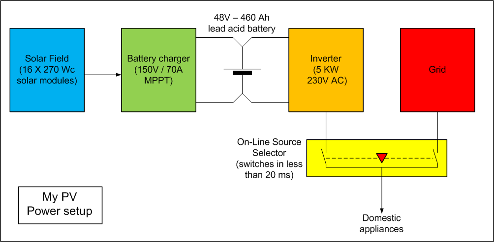
My PV (Photo Voltaic) System comprises the following main parts :
- the solar field made of 16 solar modules providing 4300 Wp (Watts - peak) of electrical power
- a solar battery charger converting the 120 V panel output voltage to 48 Volts battery voltage
- a lead acid battery pack providing energy during night time
- an inverter transforming the 48 VDC voltage provided by the battery to 230 VAC - 50 Hz for the home appliances
- a home made On Line Source Selector, capable of switching between Solar and Grid power within 20 ms
How does it work ?
During daytime, the 960 cells of the Solar Field convert the sunlight (the photons) into electricity. The efficiency of this conversion is 17%. This seems a poor figure, but as the solar power can reach up to 1000 W/m², the Field produces 4300 Watts in these conditions. This is equivalent to the power of 7 horses. Not so bad ! The Solar panels are Yingli Panda 270 Wc modules.
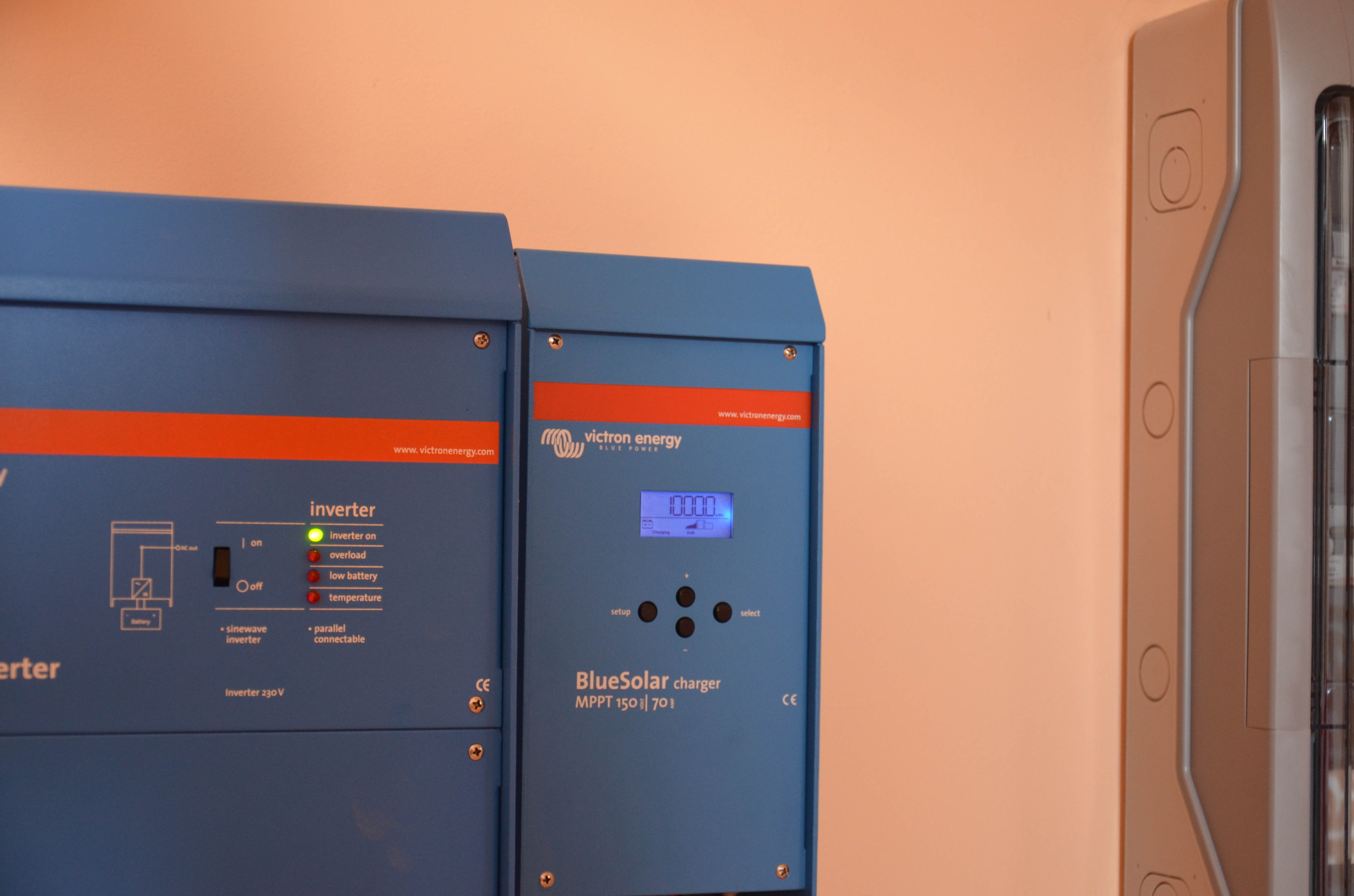
The Battery charger converts the high voltage (120 Volts DC) coming out of the Solar Field into 48 V DC, suitable to battery charging. Due to the continuously changing solar light power, the charger tracks the maximum power point continuously in order to optimise the system's yield. The Battery charger also manages the charging process of the Battery. This device is the most elaborate part of the system. The charger is a Victron Blue Solar Charger 150/70 MPPT .
The Battery gets loaded during daytime and discharged during night time. It can store up to 10 KWh of electricity. This is enough for one day of consumption. This is a short time, but it's weight is still 500 Kgs (1/2 ton). I expect a lifetime of at least 7 years for my batteries. The batteries are 8 Vipiemme 12V/230 AH semi stationary batteries. Increasing the capacity of the Battery pack, without increasing its weight and size is an important challenge for the future.
The Inverter converts the 48 VDC battery voltage into 230 V AC. The rating of the Inverter is 5KW permanent and 10 KW during 5 minutes. Thanks to this large rating, we can use all the classical "energy eating" house appliances like the electric kitchen oven, the dishwasher, the washing machine and even the clothes dryer. When the Inverter supplies 10 KW, the battery current may climb up to 200 Amps. The Inverter is a Victron Phoenix 48V/230V 5KVA inverter.
The Grid is the public electricity network. In France electricity is mainly provided and distributed by EDF (Electricité de France). Nuclear Power Plants produce currently 85 % of the French electricity. To my opinion, electricity is (very) cheap: about 0,12 €/KWh. One can bet that this price will rise a lot once it's time to dismantle the many french worn out nuclear plants. Our children will probably have to pay the bill.
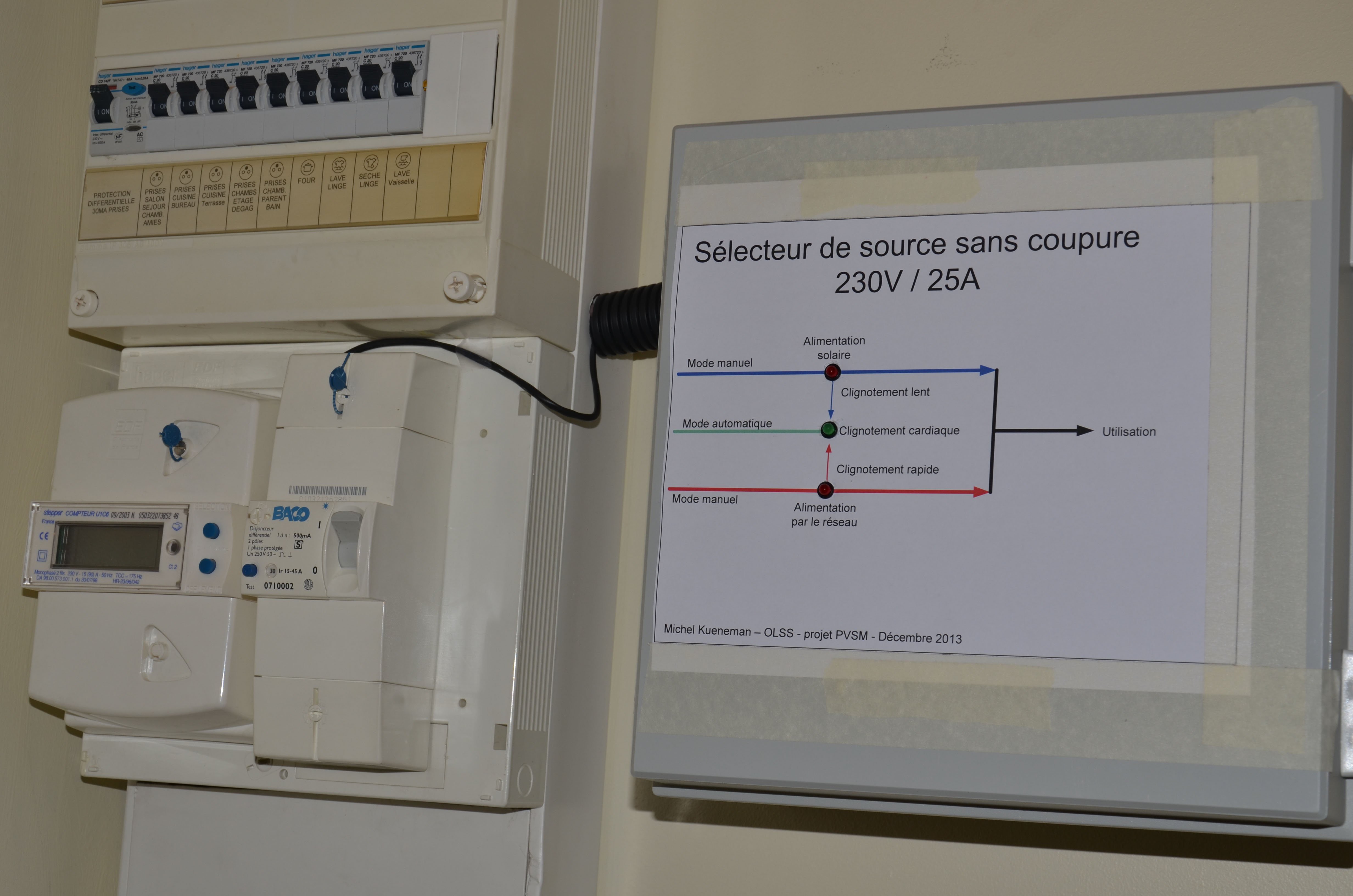
The Source Selector is able to switch between solar energy and Grid energy nearly instantaneously (less than 20 ms). This insures that the energy source change is generally unperceivable to the inhabitants of the house. This prevents also PC and electronic device crashes. The source switching occurs when the battery is too discharged to go on using solar energy, or when the battery is charged again after a dull day. The design of the Source Selector prevents paralleling of the solar system with the Grid at any time. The Source Selector is a fully personal design.
A few pictures of the System:
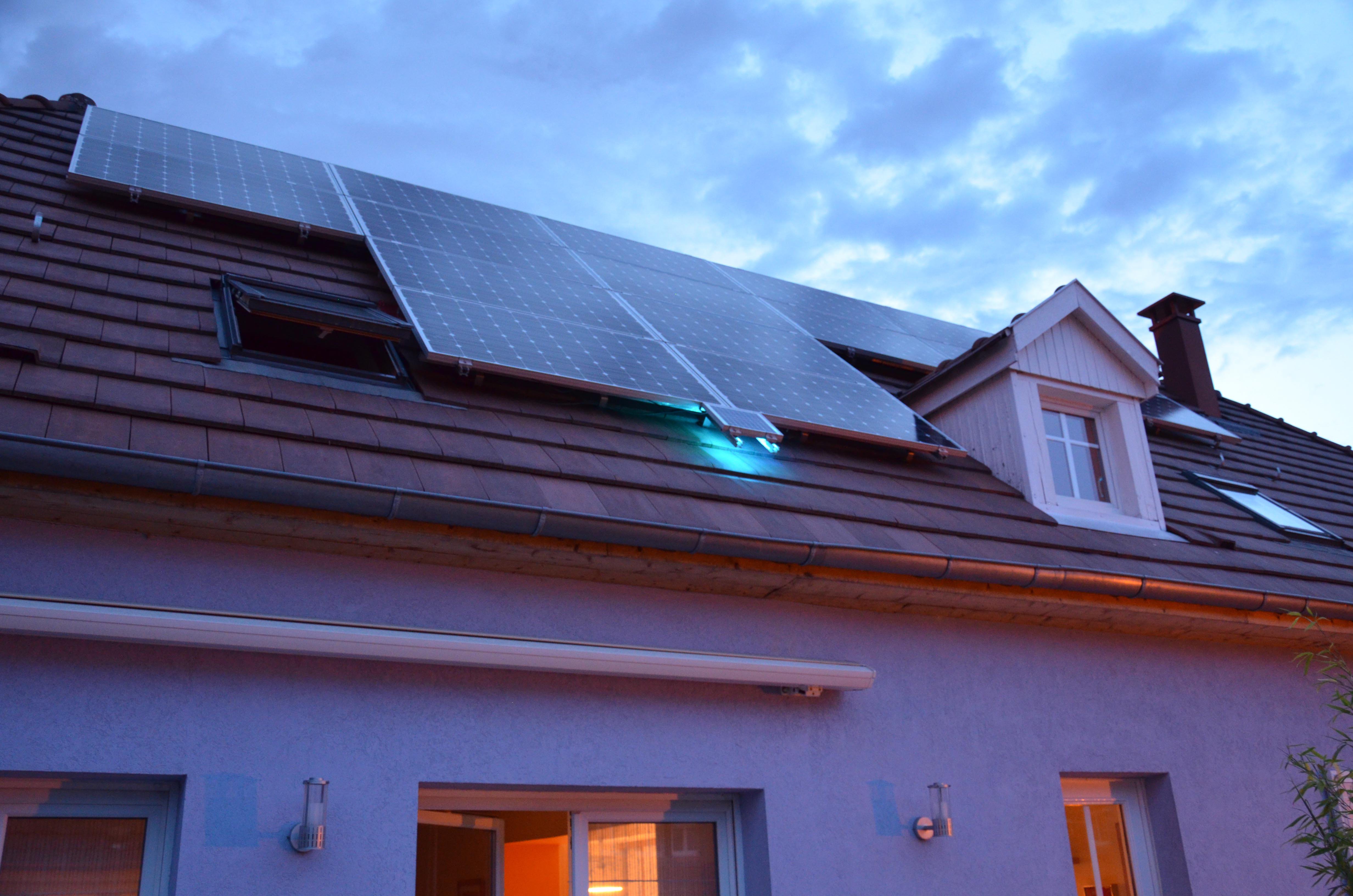
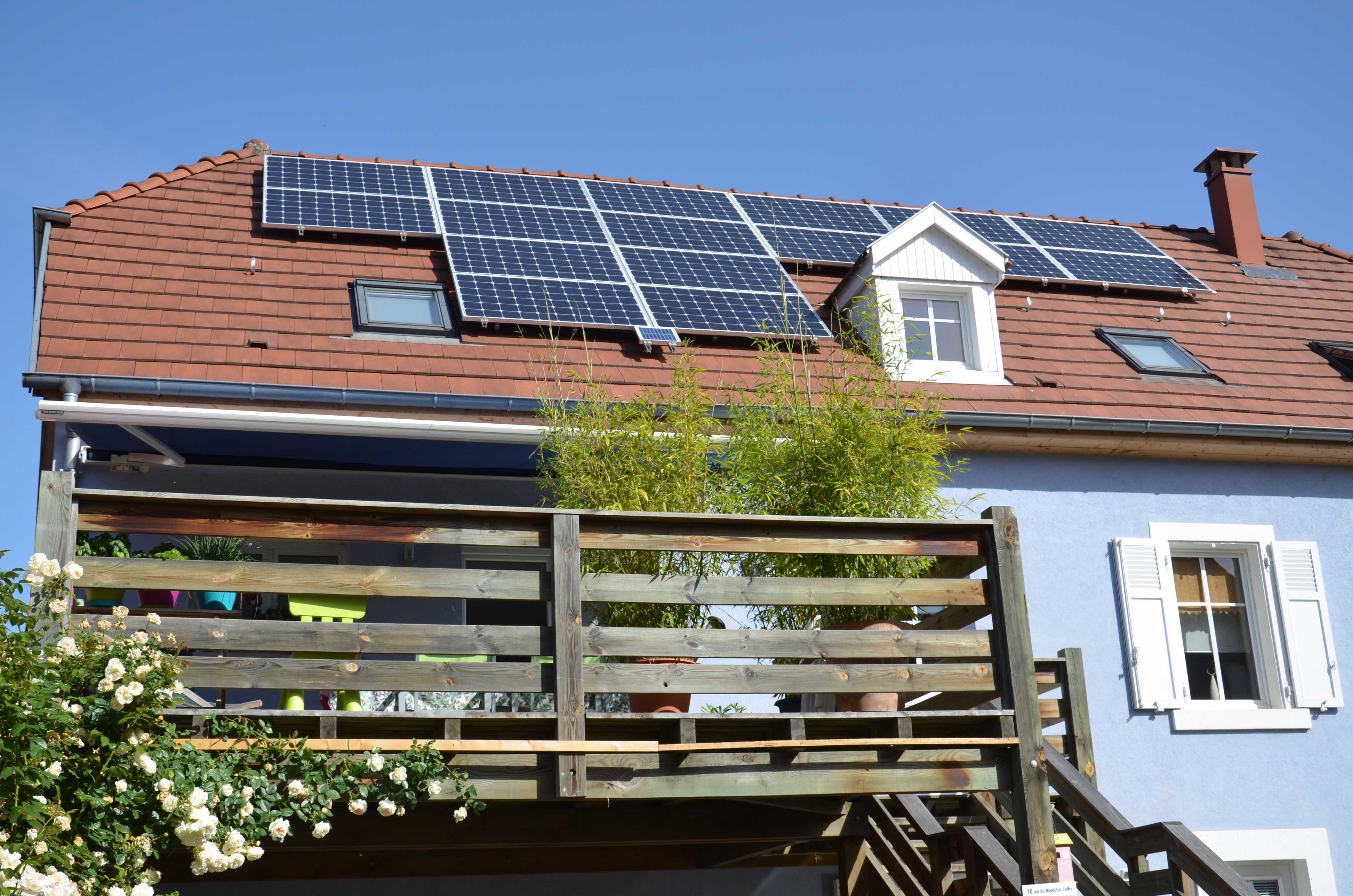
The complete Solar Field
The small panel at the center bottom is the measurement panel. This panel measures the available solar power at any time.
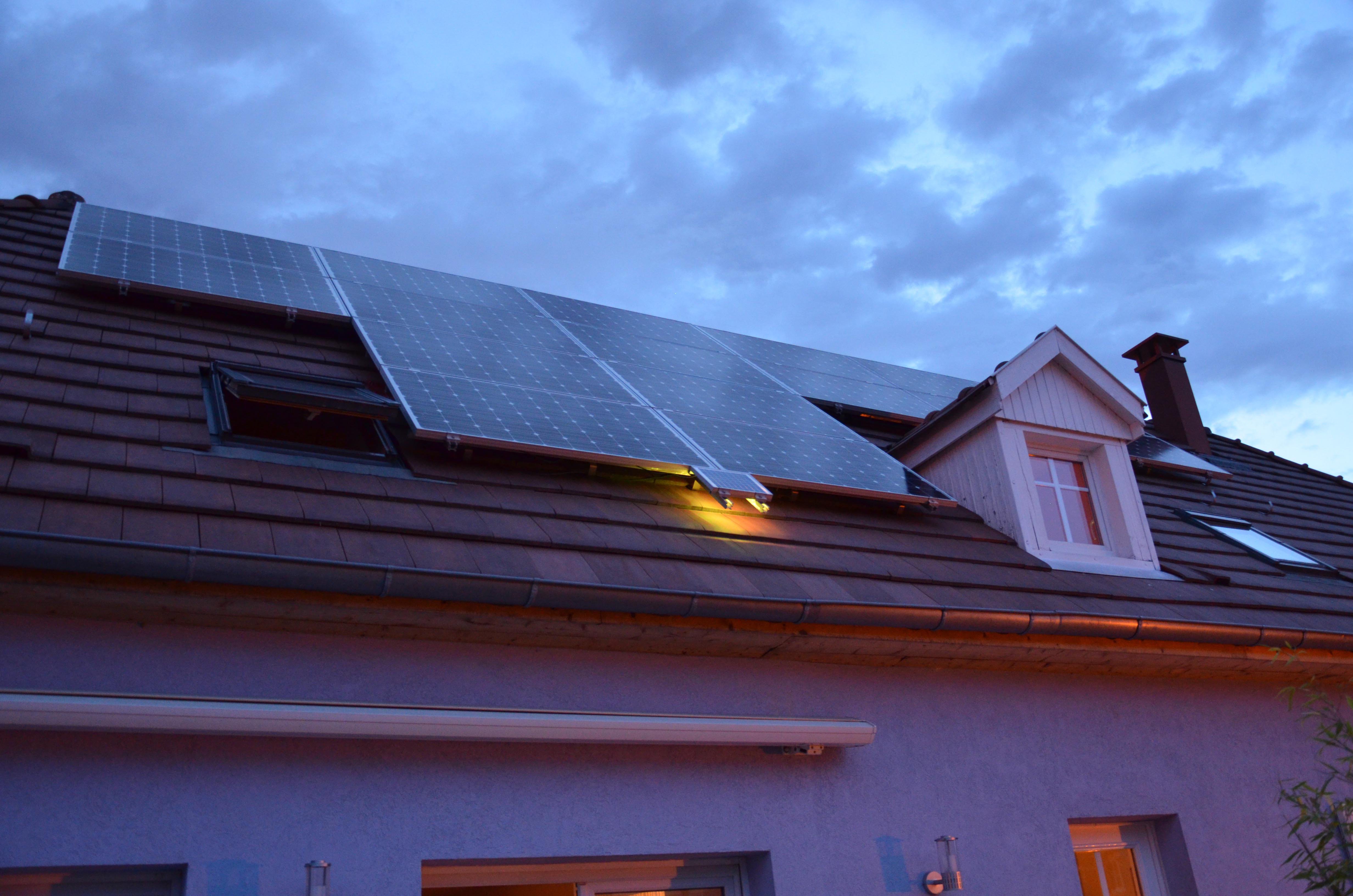
At night, a lighting indicates whether the house is supplied by the PV System (Cyan - Blue) or by the Grid (Yellow - Red)
| The house is supplied by the PV System | The Grid is currently supplying the house |
|
|
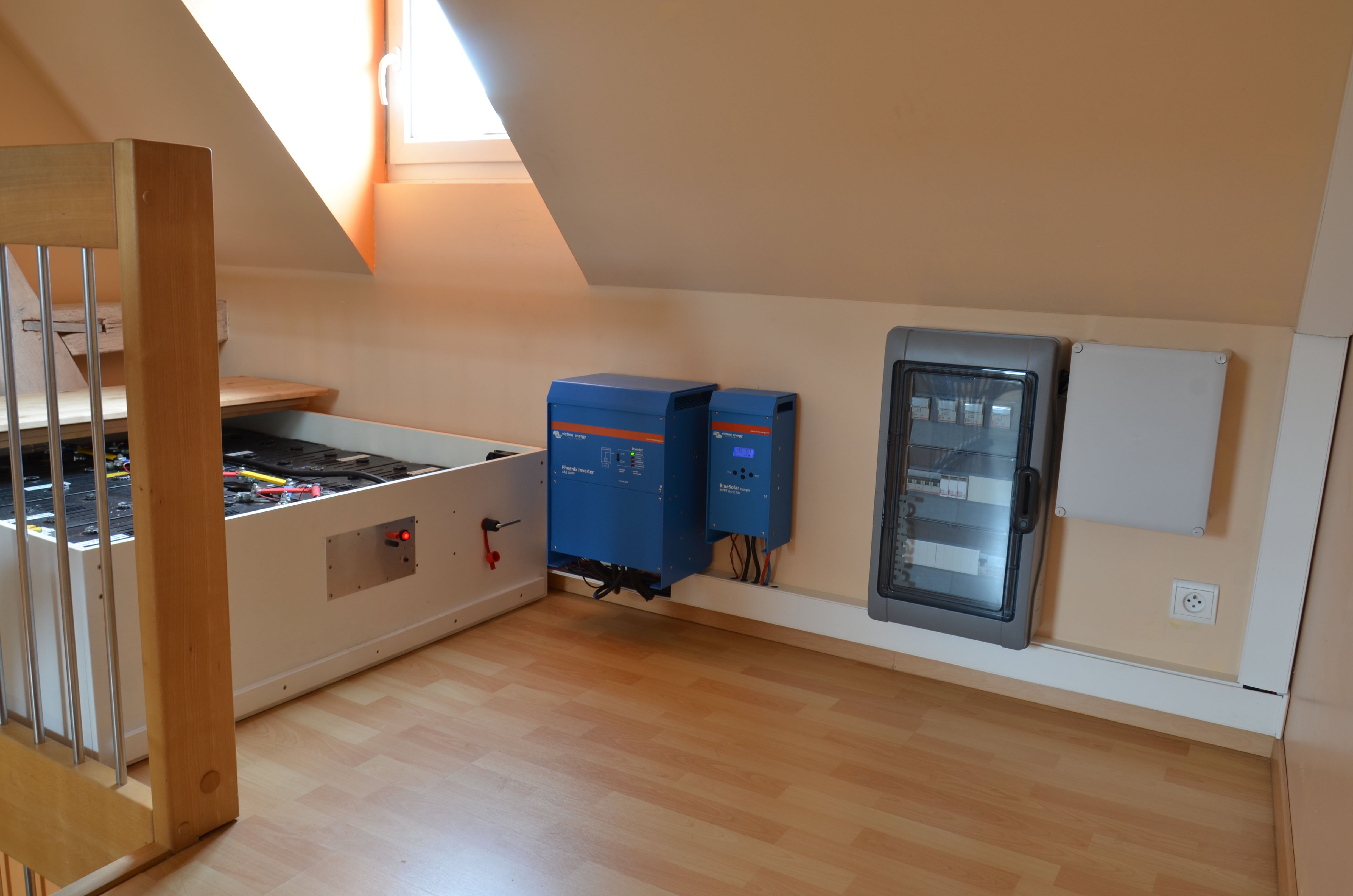
Inside the house: the battery pack, the inverter and the solar charger (left to right)
The large grey box contains the fuses, circuit breakers and lightning protections. The small one contains the PV Field Monitoring board (PVFM), the Raspberry Pi hosting the database and the Web User Interface and the CAN bus backbone.
| The Charger indicates the first produced Megawatt Hour in May | The On-Line Source Selector |
|
|
The monitoring system (= System Design Document)
My goal was to acquire accurately each single voltage and current present at any stage of the system. As this would have been very difficult to achieve with a single acquisition board, I have decided to design a distributed architecture using a dedicated acquisition board for each main part of the system. Communication between the boards is performed by a CAN bus working at 500 Kbits/s.
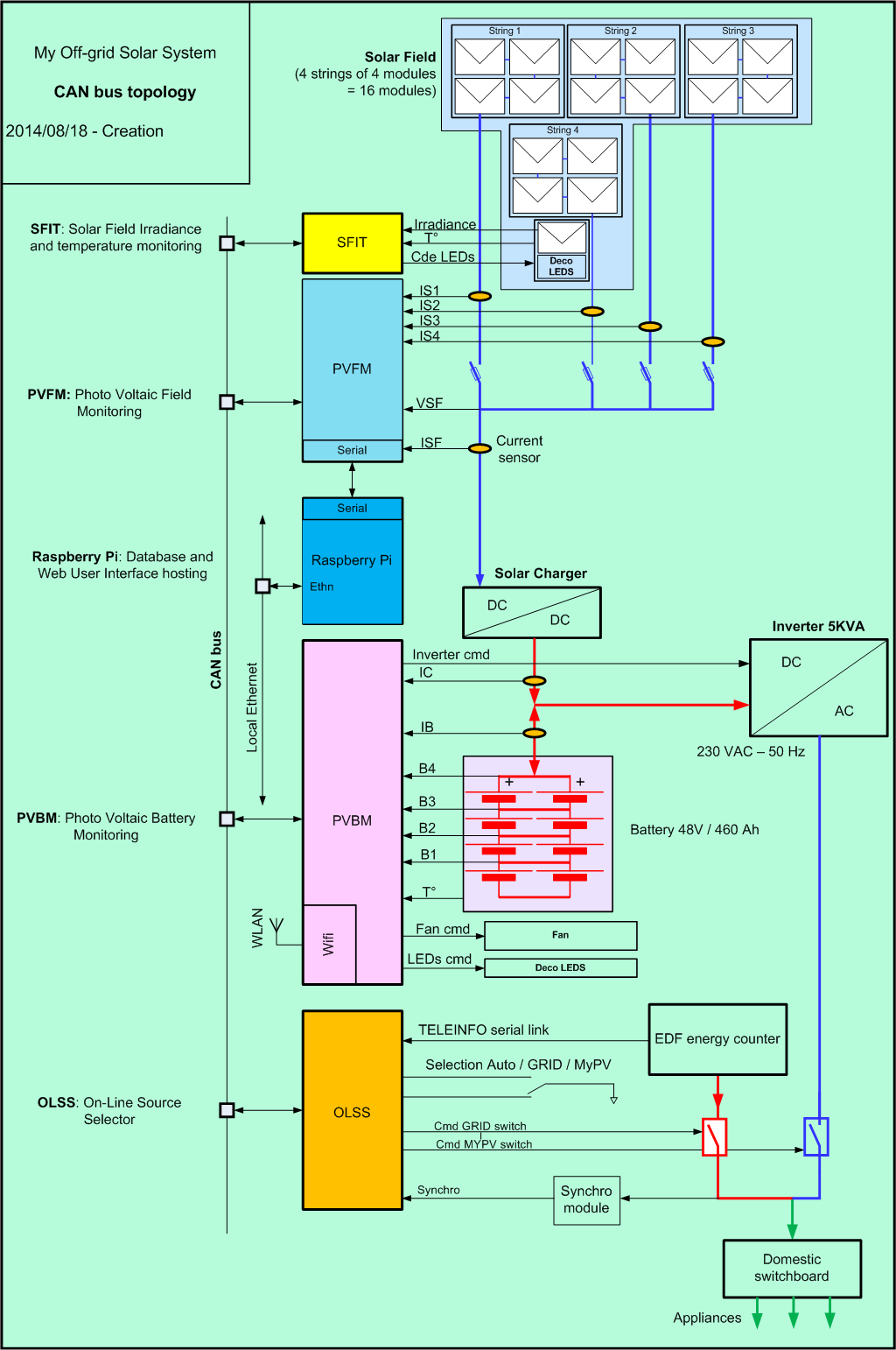
The monitoring system comprises following modules and boards:
- Solar Field Irradiance and Temperature module (SFIT): Connected to a dedicated small measurement PV panel. Measures the available solar power (irradiance) and the temperature of the field.
- PV Field Monitor board : acquires currents the and voltage provided by the solar modules organized in 4 strings of 4 panels. Acts as a gateway between the CAN bus and a serial port.
- Raspberry Pi : acquires data available on the CAN bus and stores them in a data base (RRDtool). Hosts the MyPV Web Server. The Rpi is wired to my home Ethernet network.
- PV Battery Monitor board (PVBM) : acquires battery voltages, current and temperature. Manages the automatic switch between MyPV and Grid power depending on the battery state of charge. This module is equipped with a Wifi module acting as a gateway between the CAN bus and the Ethernet.
- On-Line Source Selector (OLSS): switches between the MyPV power and the Grid power in less than 20 ms. This device is controlled via CAN bus messages.
Following drawing shows how this is organised around the CAN bus :
The Human-Machine interfaces (HMI)
None of the boards and modules of the monitoring subsystem provide any interface with the user (but a few activity LEDs).
This is on purpose: as this system shall be remotely controlled and supervised, the whole HMI must be available through some "up to date" remote capable means, like an Android application and/or a Web User Interface (WUI). Any effort put in local HMI would have been unproductive in this perspective.
In fact, I have developed both types of interfaces during the last year :
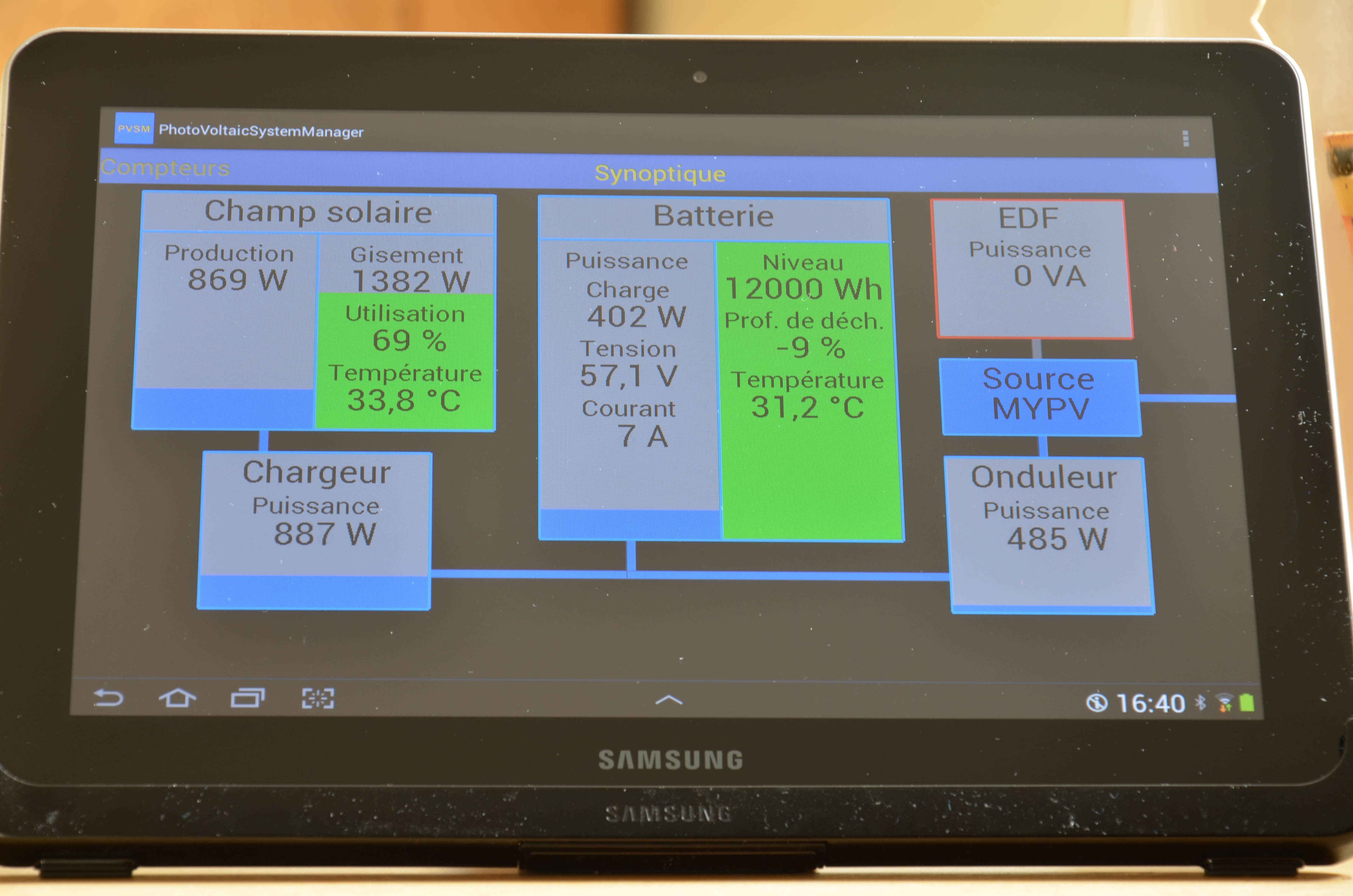
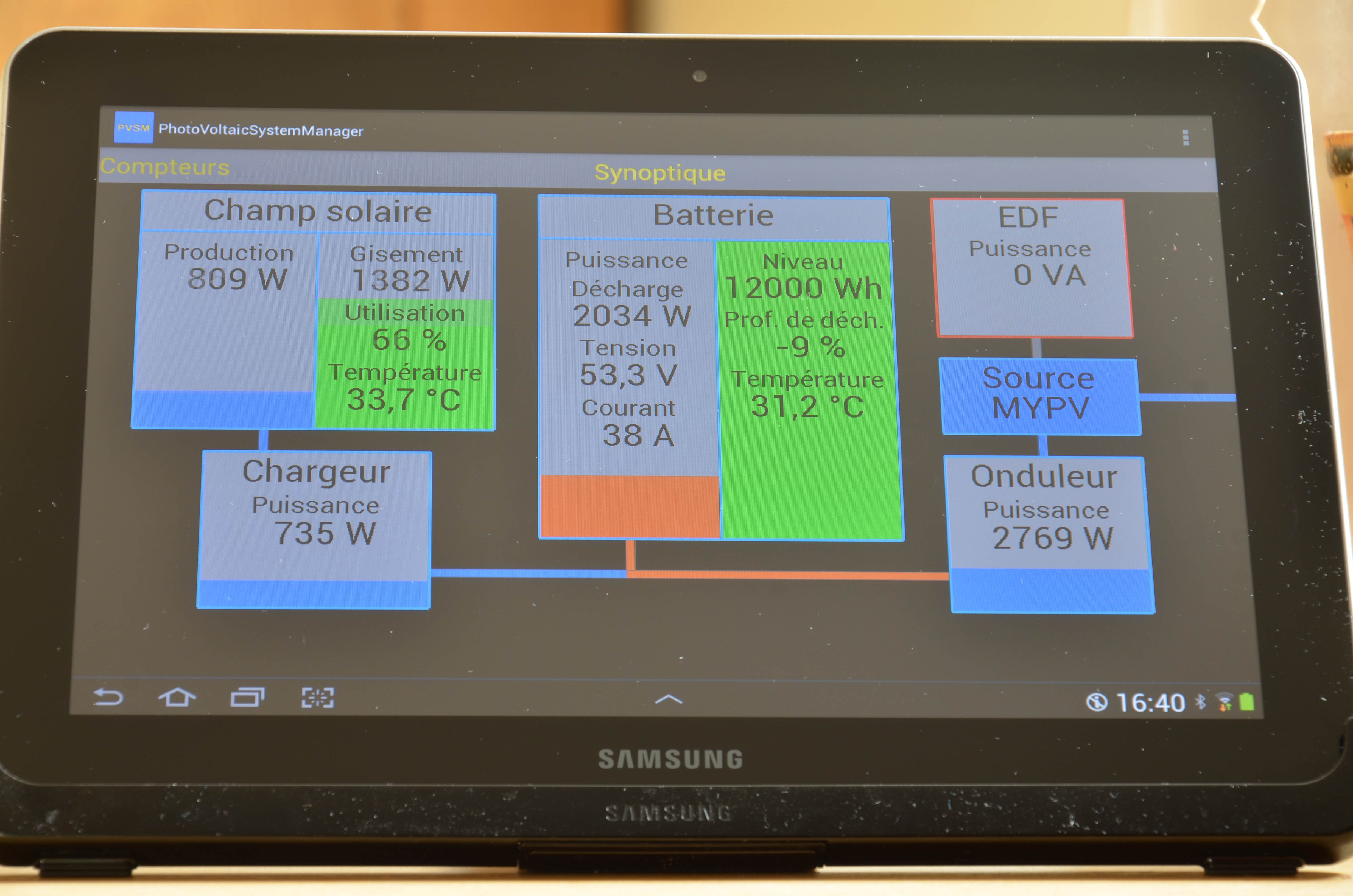
- The PV System Manager (PVSM) Android application: this app provides the user with "real time" interaction with the system. This app works locally and anywhere, provided Internet access is available. This a true "peer to peer" application. It can be run on only one device at a time. As it allows control of the system, this app is private and will never available on Google Play :-). Nevertheless, the Java project is open source.
- The MyPV website: This dynamic site is hosted by a dedicated Raspberry Pi. The built in RRDtool data base captures the data available on the CAN bus on a minute time basis. Python scripts create valuable charts allowing the user to figure out the state of the system "at a glance". The "Selection" tab gives access to a "custom brewed" chart. The user can chose among 40 different data to display.
The Android PVSM application executing on a 10" tablet
| The battery is currently charging with a 7A rate (trickle charge) | The battery is currently discharging with a 38A rate |
 |  |
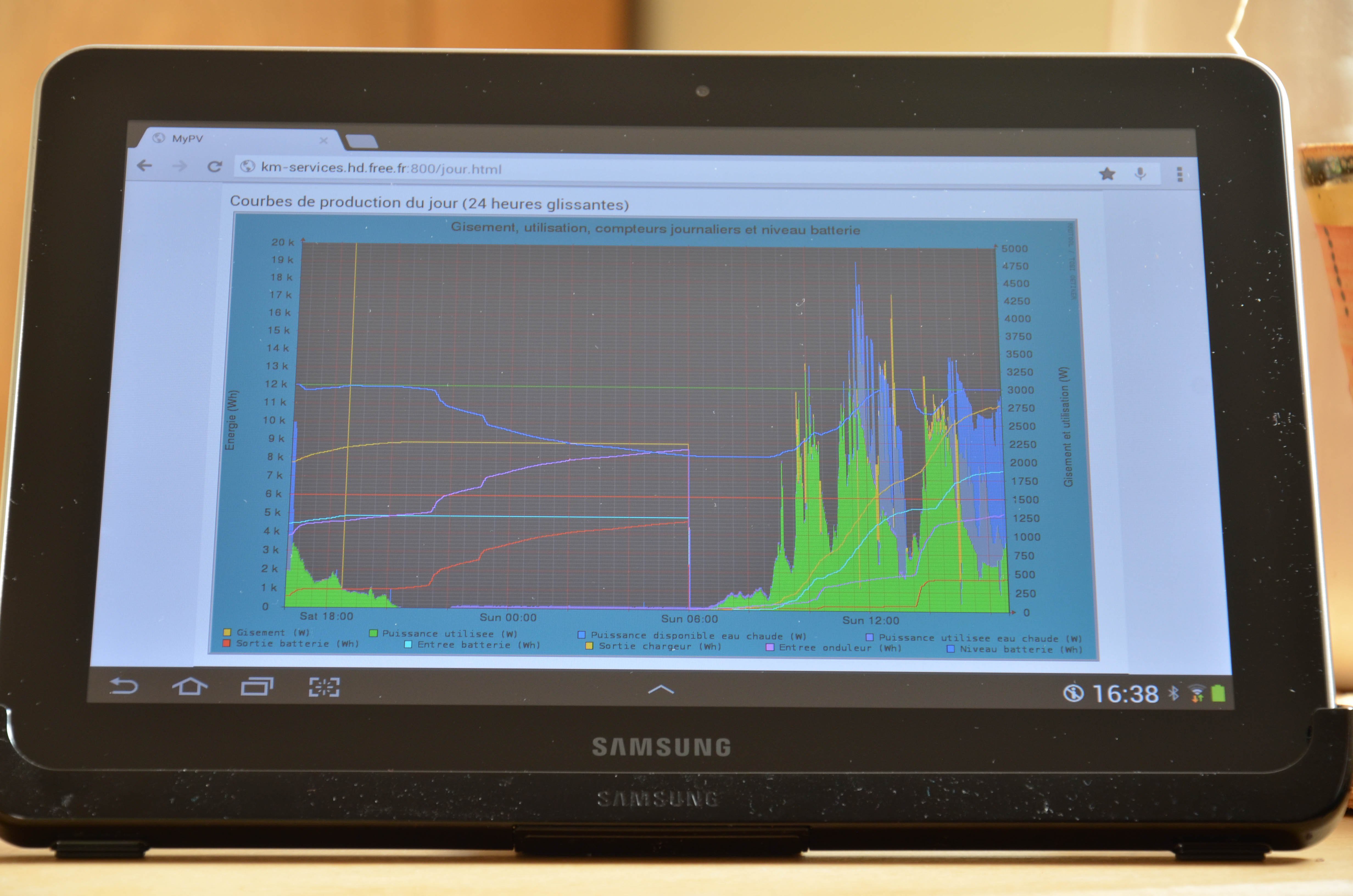
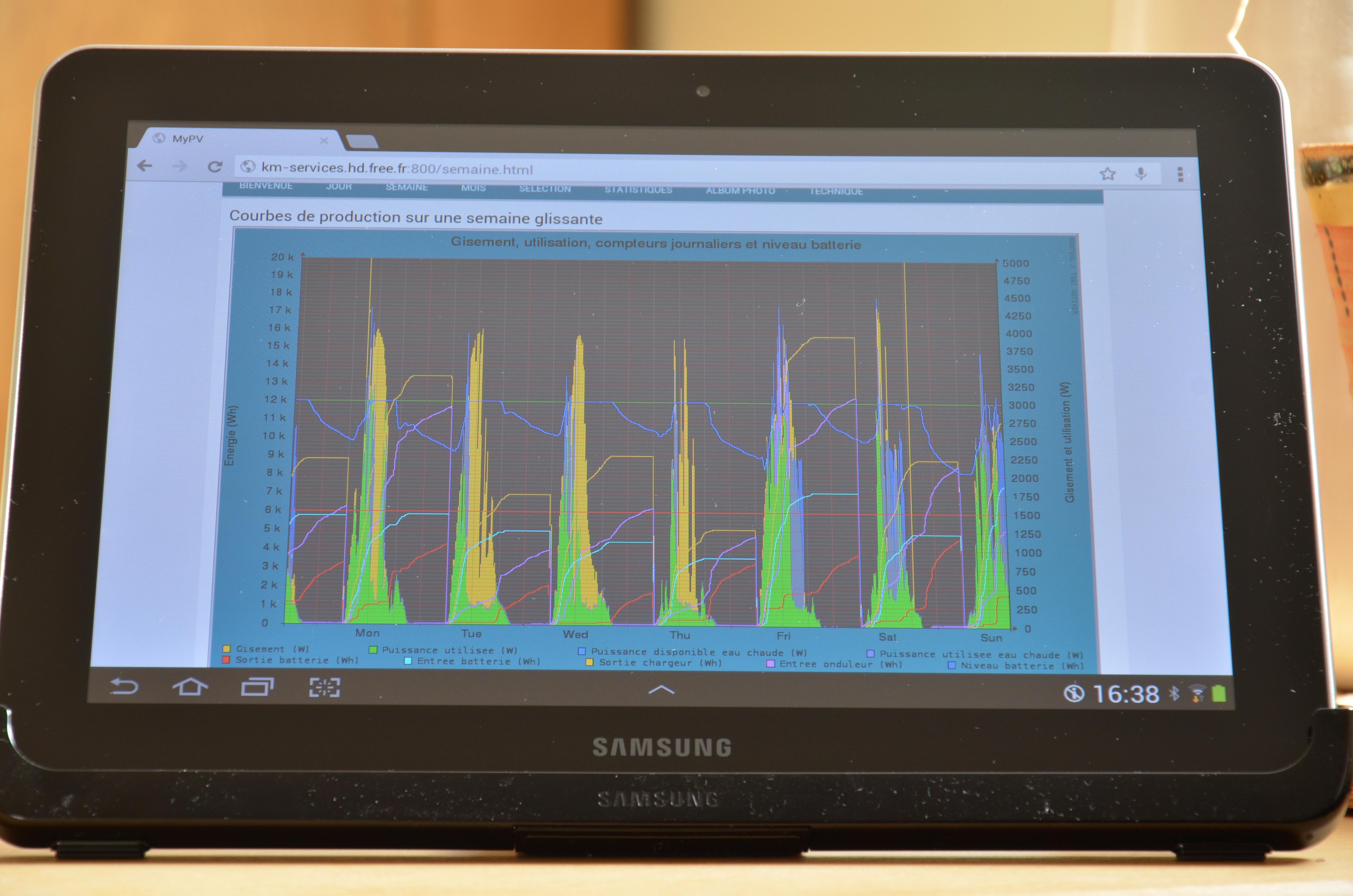
The daily production chart displayed | The same tablet displaying the weekly production |
|
|
 Michel Kuenemann