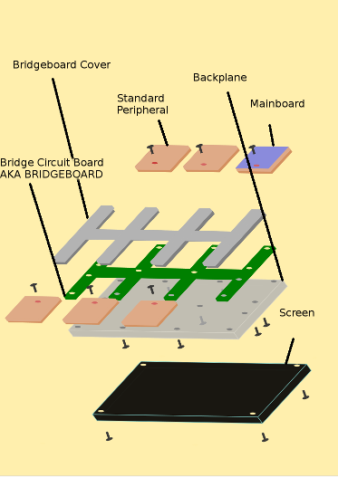
I am finishing partial schematics for this bridge and I feel if anyone else wishes to base their design or give me any ideas on this I should set up a few ground rules. I am setting these rules based on the limitations that I have found that are affecting the people I am basing my design for. These people have different jobs and tastes that require them to all have some limitations. These limitations seem revolve around similar areas, and they need to be taken note of. I also haven't shared what this should be capable of. So I will list what this device should be capable of doing, and I will progress from there. Here is the crude exploded diagram partially labelled. I will start with the basic specs of of the bridge. This is what I am working with right now

THE BRIDGE
Communication
*****By default the Mainboard should have control over the USB Hub no matter what position that it is plugged into on the Bridgeboard. The Mainboard also has control over the power system through I2C or the preferred protocol. The Mainboard must be compatible for the current generation of tablet.
***I am going to be moving from FullSpeed to HighSpeed after this iteration, and then bring in SuperSpeed when SoC devices can handle the
new USB 3.1 standard. After that when MIPI is a more formalized standard I will look towards that, but that is only if it's practical.
*****The mainboard should have control over every device on the board. It should be able to exercise power over the power system, and it should be able to disconnect any device from the system. All devices will have to report to the power system, and the power system on the bridge should report to the bridge.
***At this moment I can not initiate the USB suspend mode as of power. I am working on that to change.
Power
*****All ports must allow batteries or other power sources to supply power between 3.7v-4.4vdc at a current level of between 400-600mAh at full charge, and each power delivery device must be able to shut down and charge when the charging port is in control of the power system. The battery must also be able to cut off/recharge when the battery has reached a critically low level. This device must be able to handle charging of the device at standard USB 5v, and must be able to handle power of between 500mAh to 1000mAh. The charger has to be able to deliver upwards of 4 ampures.
***1000mAh is subject to change on the prototype due to time constraints on circuit building (I have a week to finish a workable schematic). Full version should be fully compatible with these constraints.
-if there is only one battery on board, it must be able to supply between 600-800mAh. This is required to power the mainboard and main interfaces first, and then other attached peripherals that are permitted to run with any remaining power supplied at this rate.
-these are the default, but should be adjustable to individual usages within a suggested safety limit.
*****Devices that are receiving power must have ESD and overload protection on the power and communication lines. All power must not leave a voltage range of 4.2-5.5vdc, and should be able to safely manage current up to 1.1A. When charging is placed into the circuit there should be no significant power loss occurring at any device (there should be no disruption in normal operation). Nominal current draw for a device is between 50-300ma. Standard USB FullSpeed and HighSpeed can draw a max of 1a. USB SuperSpeed is also set to these standards.
-these are the default, but should be adjustable to individual usages within a defined safety limit.
***Maximum Power is subject to change depending on testing, but it still might be more viable to run these high power devices from an outside source of power until I can source a better battery in the same price range.
 Krinkleneck
Discussions
Become a Hackaday.io Member
Create an account to leave a comment. Already have an account? Log In.