bonafidegeek
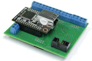
The PIC microcontroller communicates with a MAC/PHY chip to receive network traffic. The PIC keeps track of the total amount of data that is received per second. Then, once per second the data is sent to two interfaces, a serial UART to a host device and onto a LED matrix. The LED matrix displays the last 16 (8x2) seconds of network usage data.
The system diagram below illustrates how the monitor connects to an existing network using a passive tap.

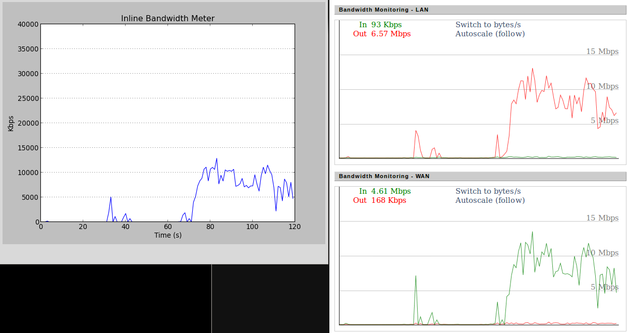
The plot below is compares the serial output (plotted in python) from the network monitor (left) against a DD-WRT plot (right).
The eagle schematic illustrates how the PIC interfaces with the MAC/PHY chip via a parallel port and to the LED matrix via a SPI interface. The eagle pcb layout has headers for power, a programmer, MAC/PHY, UART and SPI.


Source Files
Unless otherwise specified, all posted code and designs are available under the MIT license.


 Yann Guidon / YGDES