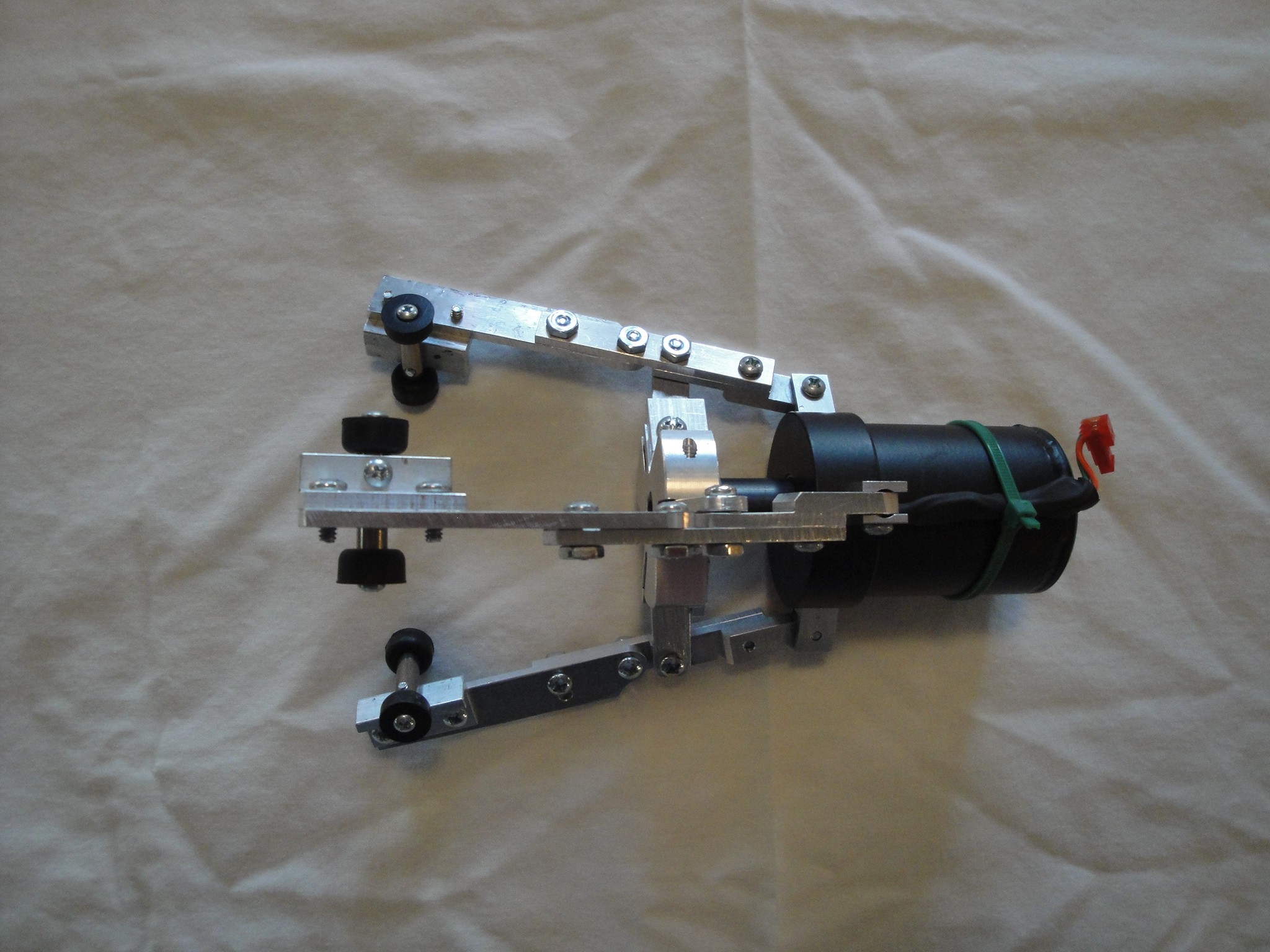
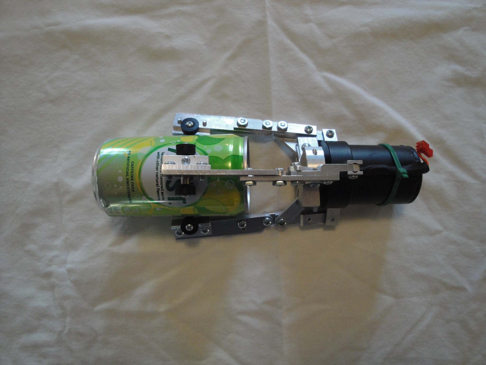
To make the claw open and close, a 24V solenoid is used to pull the plunger into the cavity and close the claw via the linkage. There is a return spring that allows for the plunger to be pushed out and open up the claws. this was added as there was too much weight/leverage of the claws and the weight of the steel plunger was not enough to overcome.
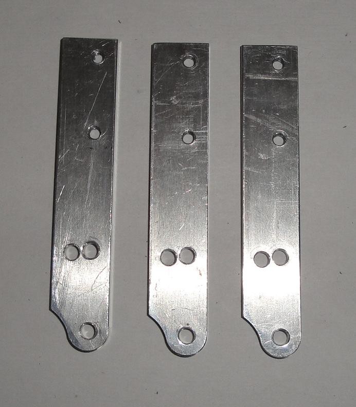
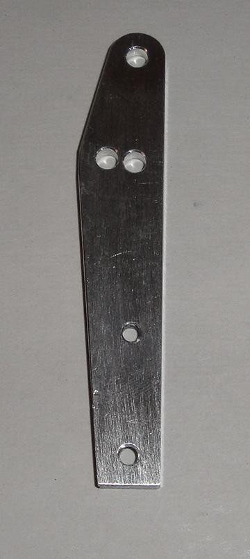
The linkage (for that matter majority of the claw) was made from aluminum but is now showing signs of galling as it has aluminum to aluminum contact. May have to change to steel parts for better wear/galling prevention, but for now it is still working.
The claws themselves are made from brake line and bent using a little tube bender that can be purchased for a relatively small cost.
The solenoid casing was turned out of some steel and is two part. An upper and lower. I added a bolt pattern on top for mounting to the wire and also a bolt pattern radially to allow for the linkage to mount to from below. It was then powder coated and then realized that the powder grew the OD and shrunk the ID causing an interference fit. It was designed to be a slip fit but is now permanently fixed to each other with the coil stuck inside.
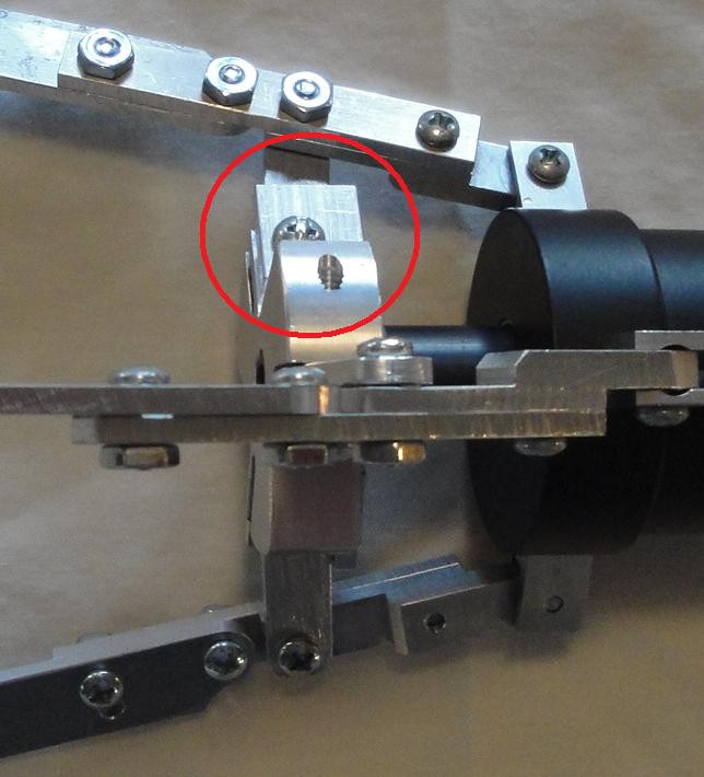
The upper mount that is used for holding the wire to the claw used a screw to thread through the eye of the wire and mounted on a small piece of aluminum. This was then pulled up into the cavity of the larger aluminum mount and able to hold the claw up with a wire.
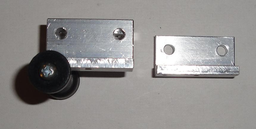
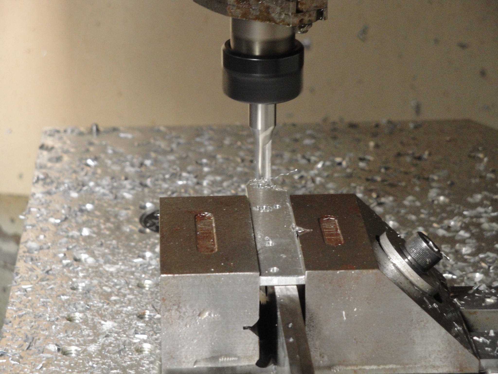
I did have access to a mill/drill and lathe and for the plunger head (aluminum) and upper half of the individual claws (also aluminum) a cnc mill. An inventive and patient hacker could put this together using a table top mill and lathe.
 willbaden
 Joseph Eoff
 Supplyframe DesignLab
 Geoff Nicholson