Andre Baptista
-
Power issues solved
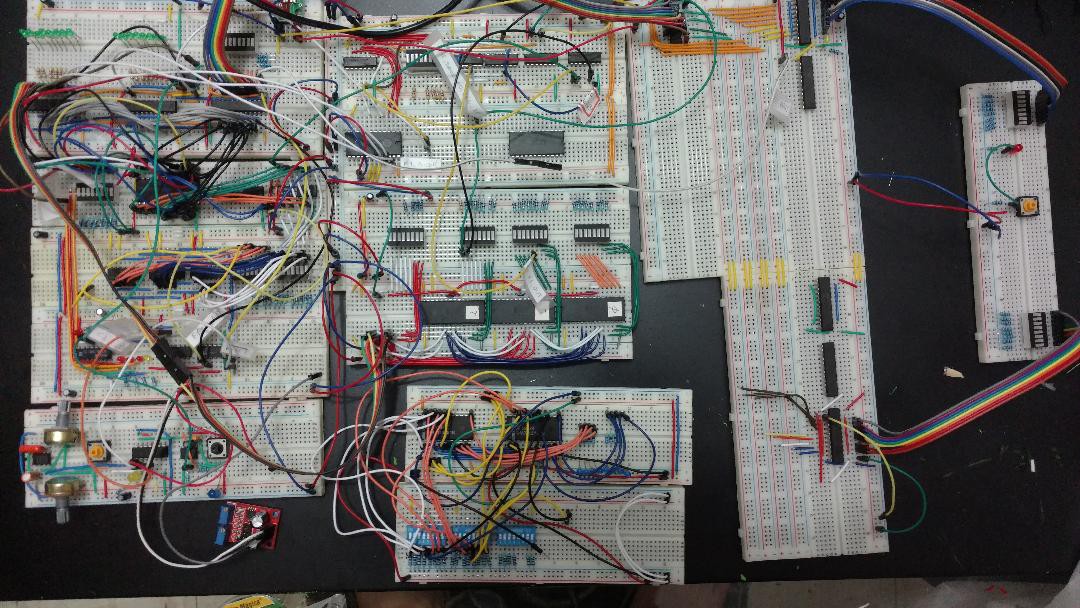
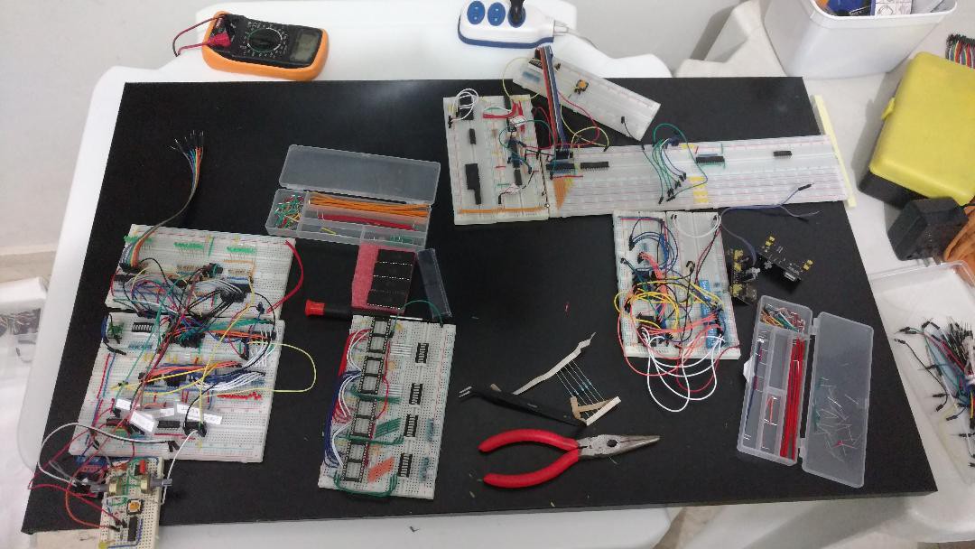
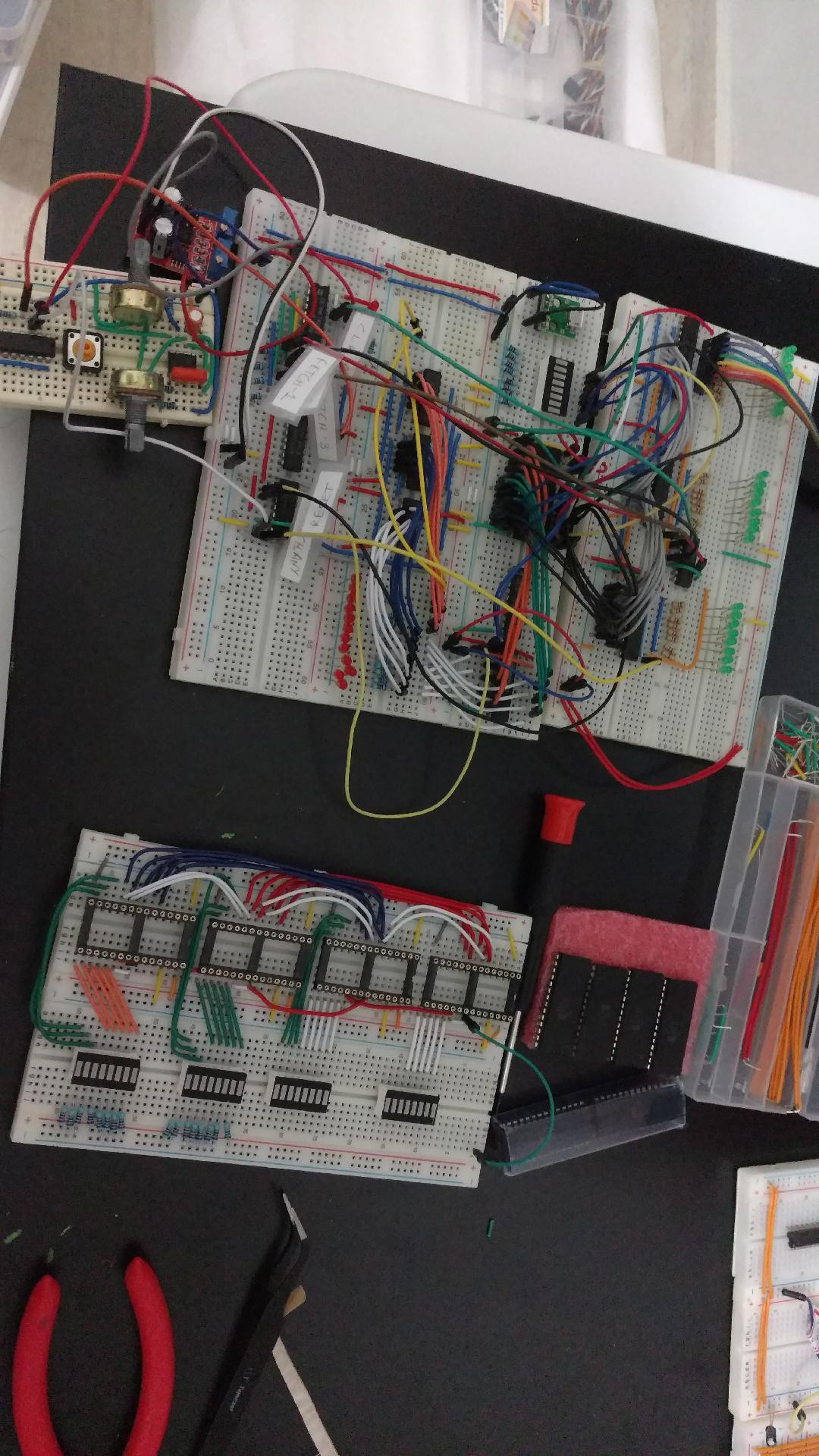
04/25/2018 at 18:38 • 0 commentsFinally I could take some time to work on the project. I improved the power grid to have the smallest number of "steps" between the power supply and each IC, and suddenly everithing works just fine, not having the issues I reported in the last log entry anymore. Even some leds looks brighter right now.
The IC 74ALS874 (8 bit register) seems to be the more sensible to lower voltages. Maybe it's common to the ALS family.
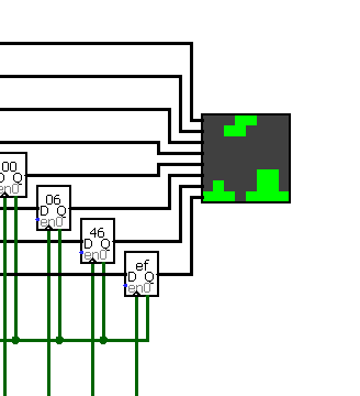
![]()
The E register is almost working (bottom right), hope I could finish it today and make arithmatic operations between the A and E registers soon.
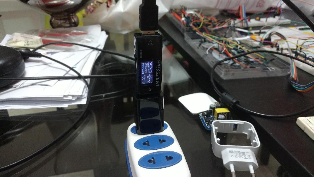
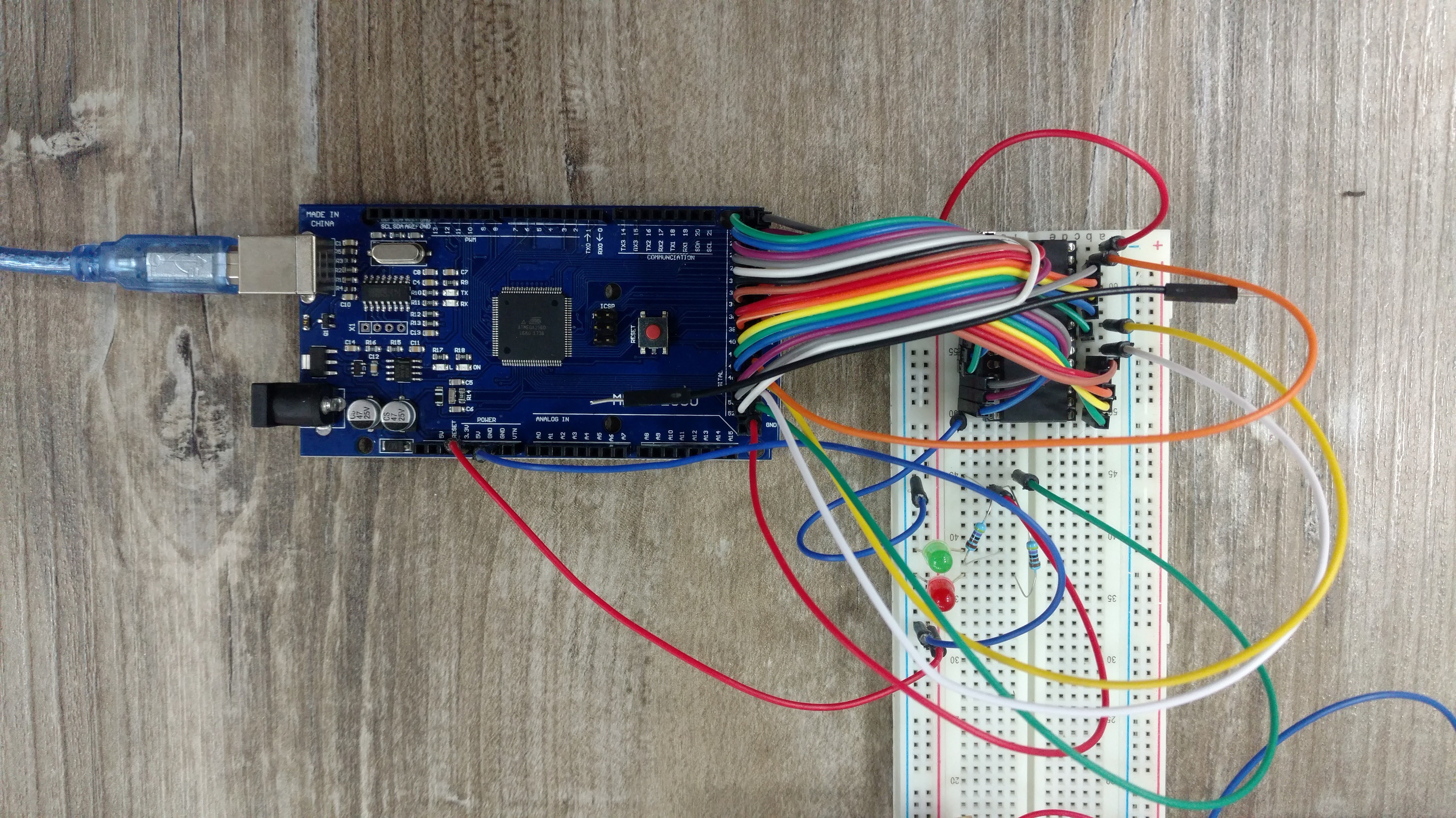
As a small note: I'm using a cheap USB ampmeter in the power supply (like this one) so I can know the current all the time (picture below). It is useful for debugging too, when you misconnect some wire and short circuit some component, the circuit frequently still works, but it's draining a lot more current. In my case it showed a rise from the normal 200mA to more than 700mA, and I could shut off imediatelly and revise the connections before to fry some IC.
![]()
Thanks for reading.
-
First instruction: loading a value into a register
04/16/2018 at 16:13 • 0 commentsThis weekend I managed to finally make the computer run a instruction from the beggining to the end.
It's a simple instruction: LD A, 0x20, that means, to load the literal value 0x20 (32 in decimal) into the register A.
Video:
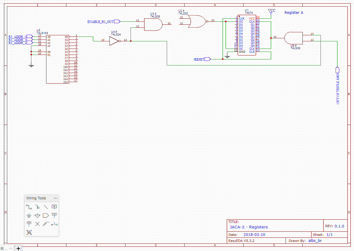
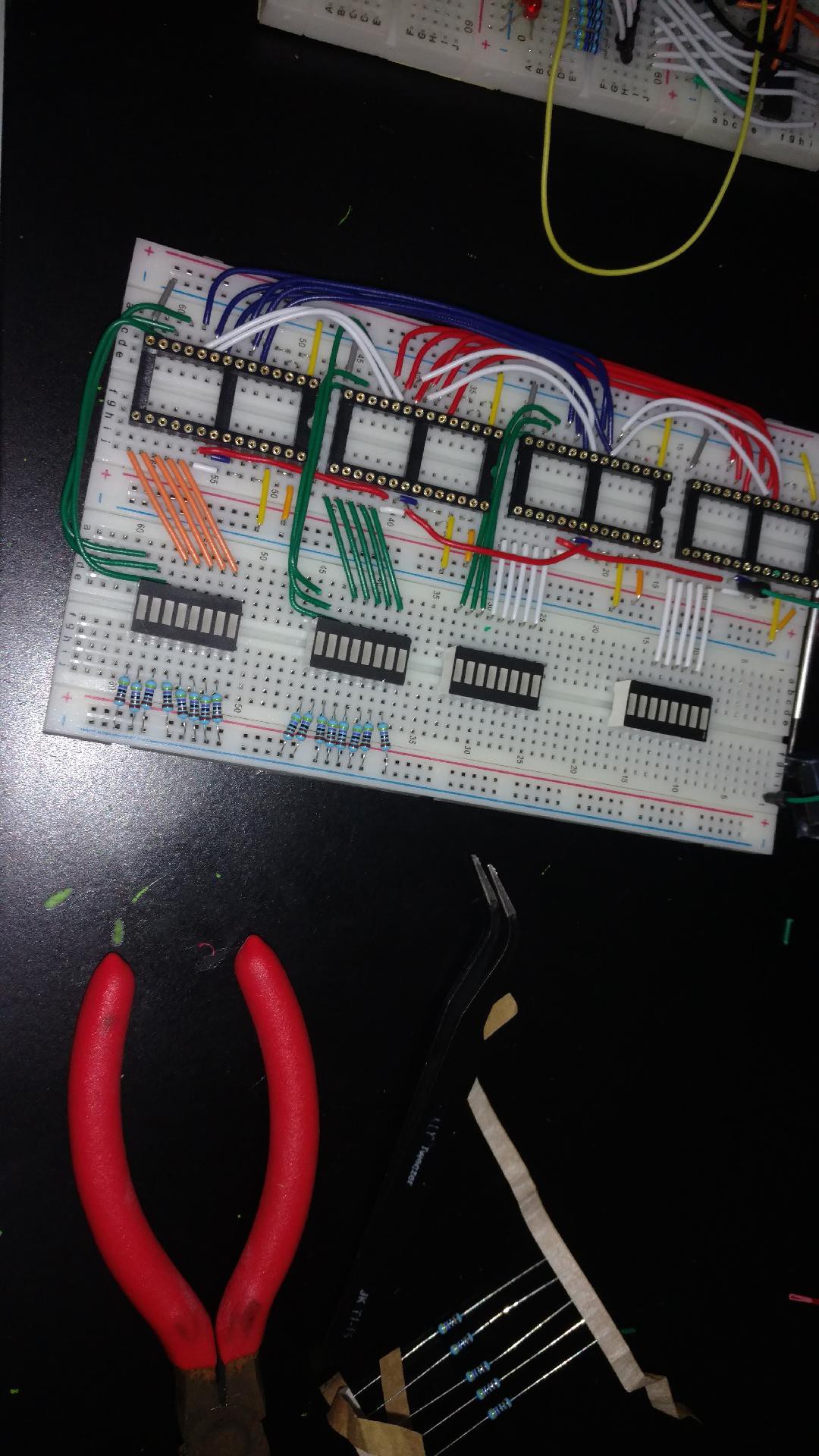
At top right is the output of the register A, displaying 0010 0000, the binary value for decimal 32.
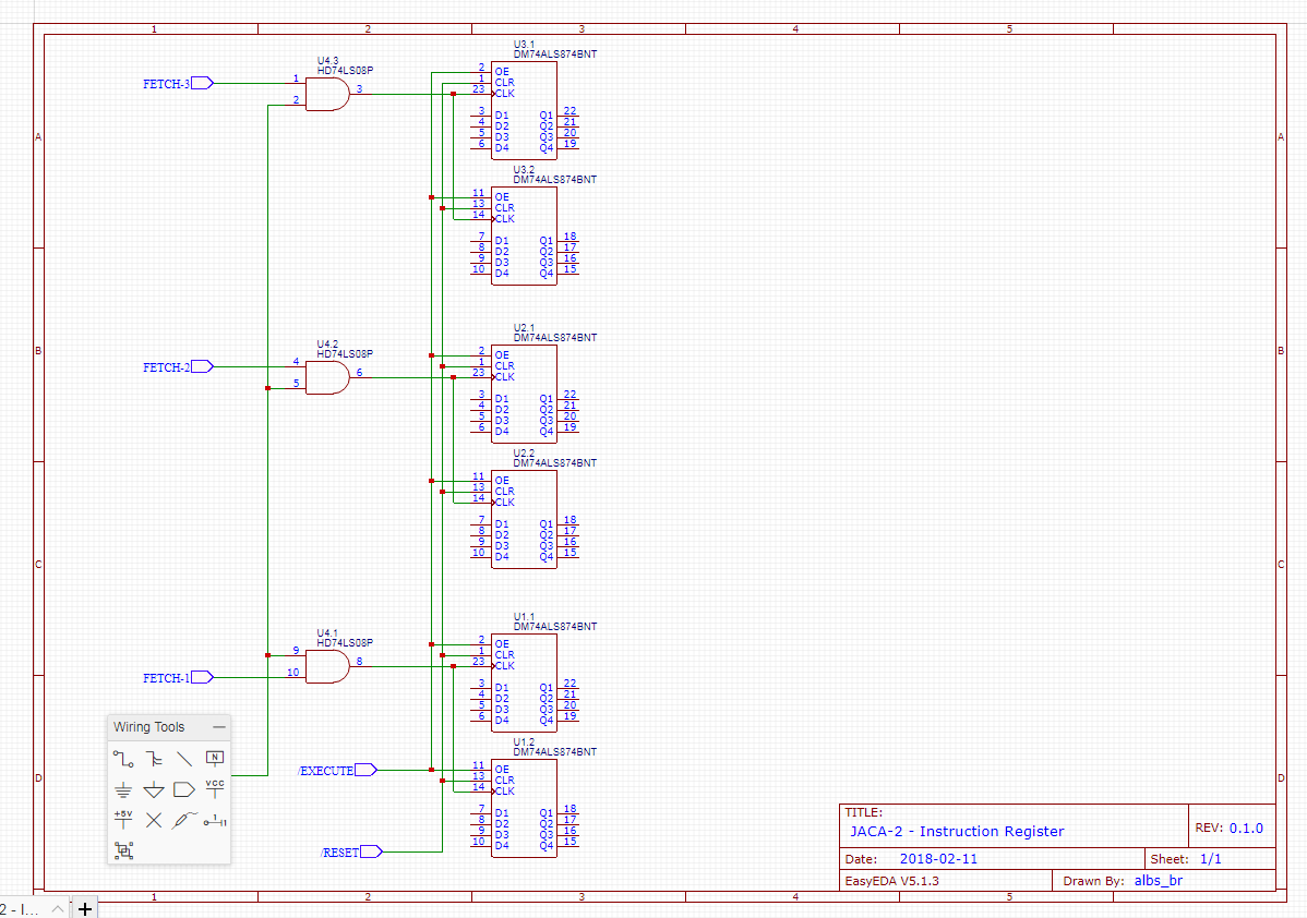
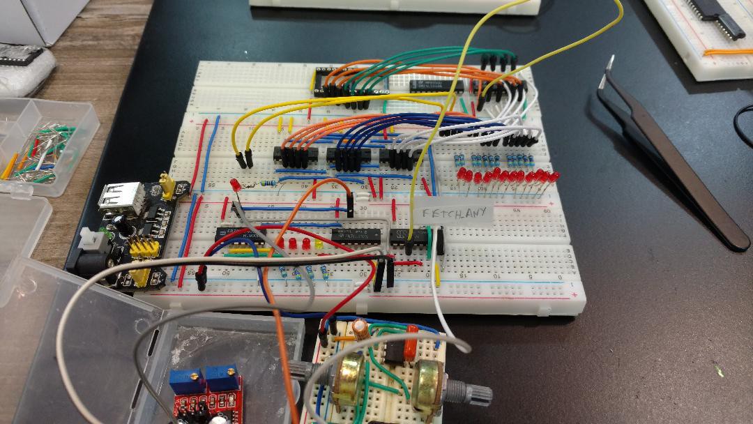
Close to bottom left are four leds, the first three red, the last one yellow. These are the sequencer leds, they show the current state of the machine: Fetch-1, Fetch-2, Fetch-3 and Execute. The fetches are the states in which the 3 bytes of the instruction are get from memory and put on the three Instruction Registers (top left corner). The green leds are the outputs of them (only shows in the last step, Execute).
But not all are good news: I also ran into two stability problems:
-The first one: the automatic clock (yellow led at bottom left) was sometimes causing the sequencer to reset, even in manual clock mode. That was solved by adding a 10uF capacitor (decoupling capacitor) to the power line close to him;
-The second: the register A is not loading the right value all the times, sometimes showing a thrash value. That is driving me crazy. I have no solution for now, but I have one suspect.
Thanks
-
Voltage issues
04/09/2018 at 12:06 • 0 commentsLast weekend I faced a (not so) unexpected problem when connecting together all modules: a huge tension drop across the circuit. The IC's fartest from power source are just under 4V! As many of you may know TTLs are guaranted to work only between 4.75 and 5.25V. Surprisingly the behaviour is perfect even at this extreme conditions, which shows how over dimensioned they are. Even the closest IC is with 4,8V.
Possible solutions:
-Use wires direct from power source to each breadboard, not daisy chaining them;
-Use a regulable power suplly and set it to 5.2V as shown in this fantastic series of the channel WR Kits: Building an 8-bit computer (in portuguese), based on the famous Ben Eater breadboard computer.
See you next time.
-
Things I learned today
04/02/2018 at 17:58 • 5 commentsTwo ideas I shamelessly stole from the fantastic Gigatron TTL:
- The MCP100/101 Power On Reset: a very common issue on most projects of this kind is that when you power up the circuit, it starts in a not-so-good state (it's not random, seems to be always the same, but it's not the initial state), so we need a small circuit called Power On Reset, to trigger a short RESET pulse when the system is powered on;
- Use the HCT family of TTL ICs instead of LS: it uses just 1/5th of the LS energy. I'm already ordering the HCT equivalents of my LS chips (when available, there is no HCT version for 74181 ALU, for example). Today the computer is using more than 200mA, not counting the ALU and registers modules. The Gigatron uses less than 90mA, but doesn't has the plethora of leds my computer has (useful for debug). Most of the leds are restricted by 4.7K resistors, making them drain just 0.7mA per led. This gives enought bright for leds in indoor use (not direct sunlight).
Thanks, and see you next time.
-
Video of computer (almost) working
03/31/2018 at 22:49 • 0 commentsApparently people have a strange interest in homebrew computers in breadboards meaninglessly blinking leds... So I made this small video (no fancy production, sorry). It lacks the register and ALU modules, so it's not doing any useful computing, just increasing Program Counter, getting 3 bytes from memory, putting them into Intruction Register and using the first 6 bits to address the Microcode Rom:
Besides this I rebuilt the clock module to include a manual clock, so I can debug step by step the computer. It will be very helpful in future.
Thanks.
-
Slow progress...
03/22/2018 at 12:01 • 0 commentsSlow project progress last month...
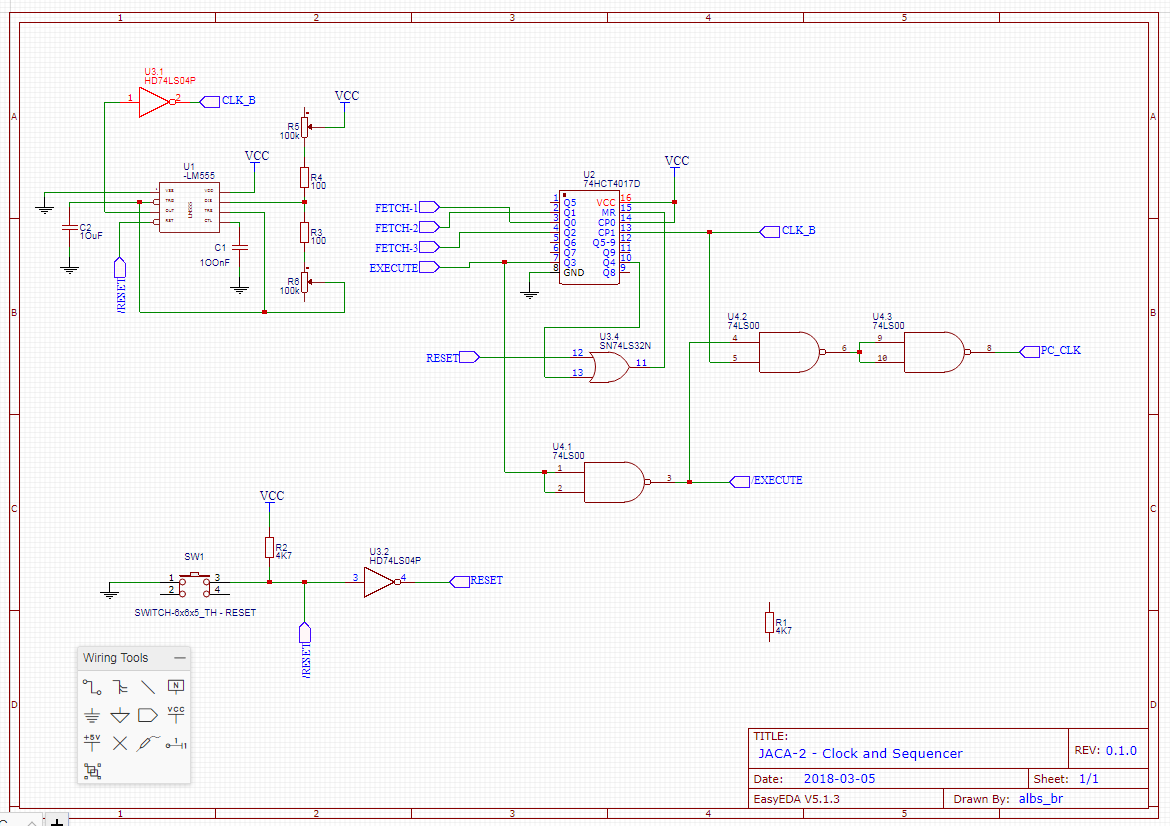
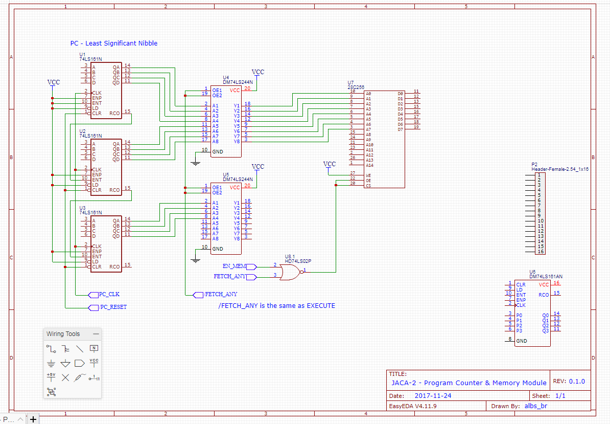
But at least I managed to finish the EasyEDA documentation of the modules (pictures below).
The situation so far: I have all the modules (a very crude version of them) finished and working on breadboards. This weekend I will try to put them together and hopefully see the CPU working for the first time outside the Logisim simulator.
By "working" I mean, capable of run one single instruction: LD A, value. That is, to load an 8 bit value in the A register (the only one avaliable).
After that, I could expand the modules, by adding registers, adding logic to connect the ALU to registers, logic to control the jumps, etc.
Thanks for reading.
![]()
![]()
![]()
![]()
![]()
![]()
-
Microcode ROM module (almost) implemented
02/17/2018 at 23:35 • 0 commentsLast weeks I implemented the microcode ROM in two breadboards:
![]()
![]()
![]()
![]()
It's not very beautiful, as lacks me patience to cut wires the exact length and right colors...
Besides that I started to document the circuit in an online tool called EasyEDA. This will be important in two ways:
- Allow to understand the circuit on breadboards (it's a bit different of the Logisim circuit);
- Make it possible to order the PCBs in the future, for a most professional version of the computer.
Links for the Easy EDA schematics (I made them public, but not tested yet):
Another improvement: finally connected the PC, memory (very crude version) and IR together. I'm very anxious to see the computer working after almost one year, even a very basic version, so I made some things simpler, and after I will improve.
Thanks for reading.
-
AT28C256 EEPROM writer
01/28/2018 at 22:12 • 0 commentsLast week I made a fundamental step to complete the homebrew computer, an EEPROM writer.
I decidede to put it in a separate project, which makes it easier for someone googling to find it:
https://hackaday.io/project/43884-eeprom-writer-for-at28c256-using-arduino-mega
![]()
Best regards.
-
Small update
01/15/2018 at 20:42 • 0 commentsSmall improvement in circuit: part of RAM memory controller:
![]()
Just to break the inertia in this part after maybe two months...
Tetris game in the 8x8 led matrix is almost on Alpha version. It's working fine, but need performance improvements to be more playable. Logisim in my computer (Core i7/quad core/8gb) is only able to achieve around 2-3 KHz. Windows monitor shows ~25% of CPU used, which makes me think Logisim don't use any kinf of parallelism (not criticising at all, it's free and was only possible by the good will of author).
-
Vacations update
01/05/2018 at 00:11 • 0 commentsDuring my vacations last december I managed to take some time to improve the Assembler, and it's now completely functional.
Also, I could program the long awaited Tetris (not finished yet):
![]()
Also I received my Arduino Mega, which with its 50+ pins will be used to make an EEPROM writer, and to unit test individually the modules of the computer.
I plan to make a video demonstrating the computer working in Logisim.
Hope this year I could finish the computer on breadboards and maybe in PCBs. Color VGA output would be great.
Happy new year and happy hacking for everyone!
JACA 1 & 2 Homebrew Computer
JACA - Just Another CPU Again Homebrew CPU, starting by a simple POC 4-bit CPU on circuit simulator soft. (done), then 8-bit (in progress)