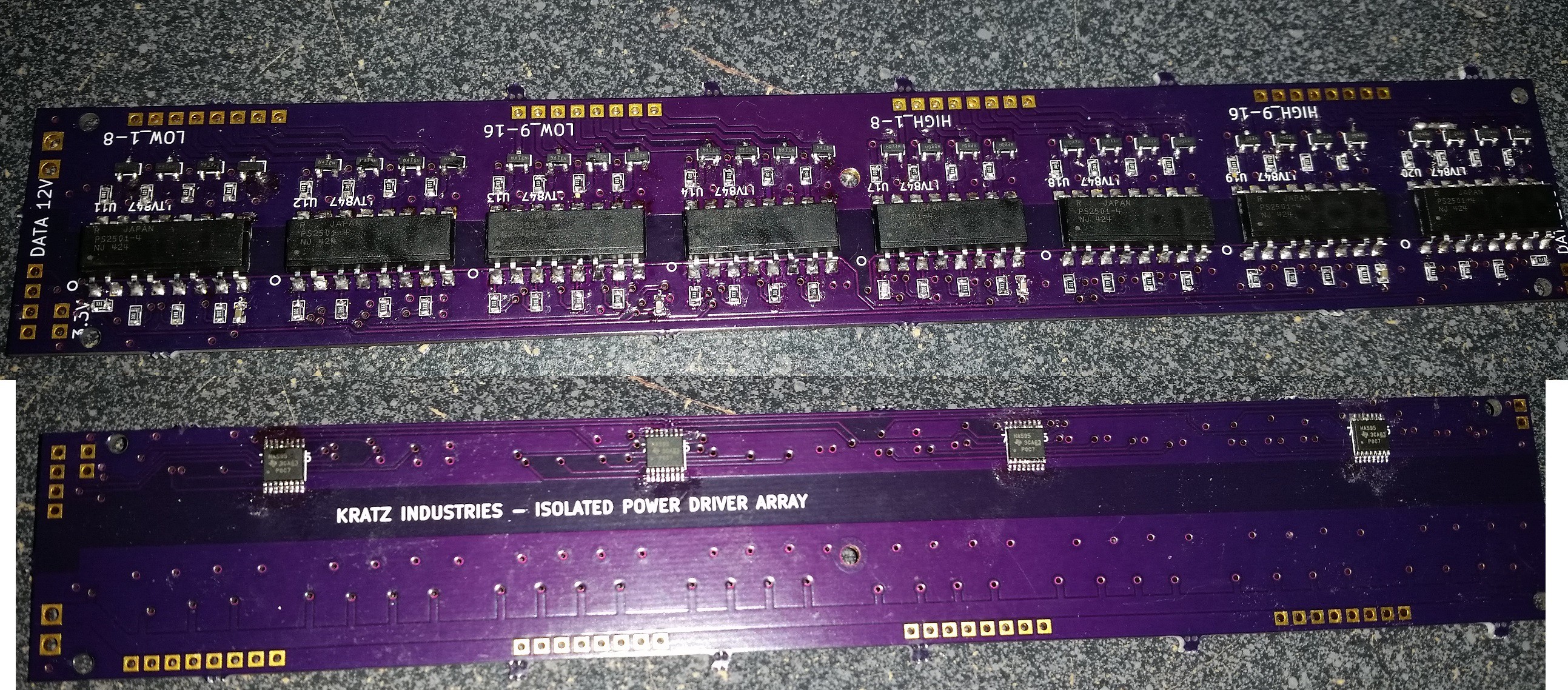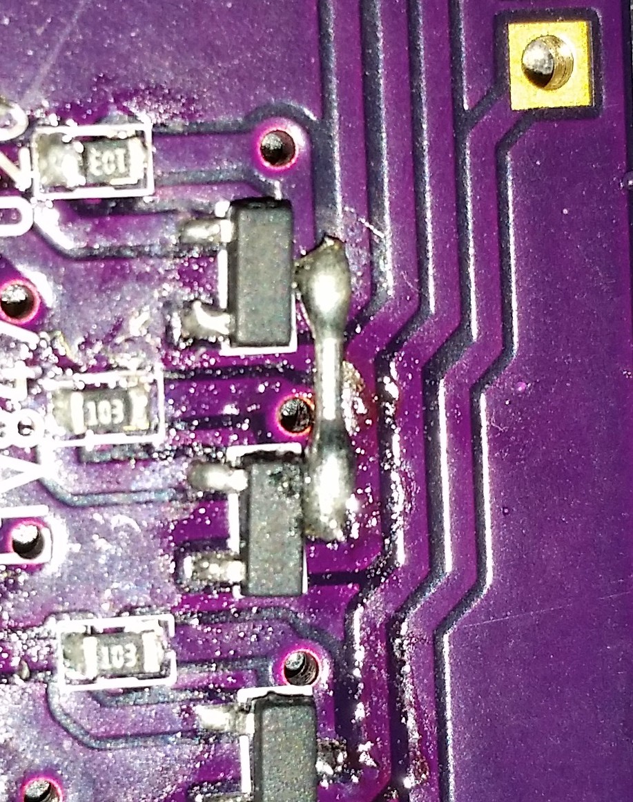
Just wanted to post the picture of my serial in driver board I made for this project. This module of the project is meant to take in serial data on the low 3.3v side, and latch it out through some opto-isolators to an array of n and p channel mosfets. 16 sources and 16 drains for a 16x16 multiplexed matrix, or whatever else you may want to do with it. The input is 4 pins, clock, latch, high data, and low data. Only one mistake, a disconnected pin that was fixed with a short jumper.

Anyways, I've ordered some small 7 segment displays from EBay, as well as a sample 3 inch 7 segment display to do some testing on. Many options for the board display, may have to go a bit smaller than originally planned for the first one. Testing the driver board is the next step for this project.
Discussions
Become a Hackaday.io Member
Create an account to leave a comment. Already have an account? Log In.