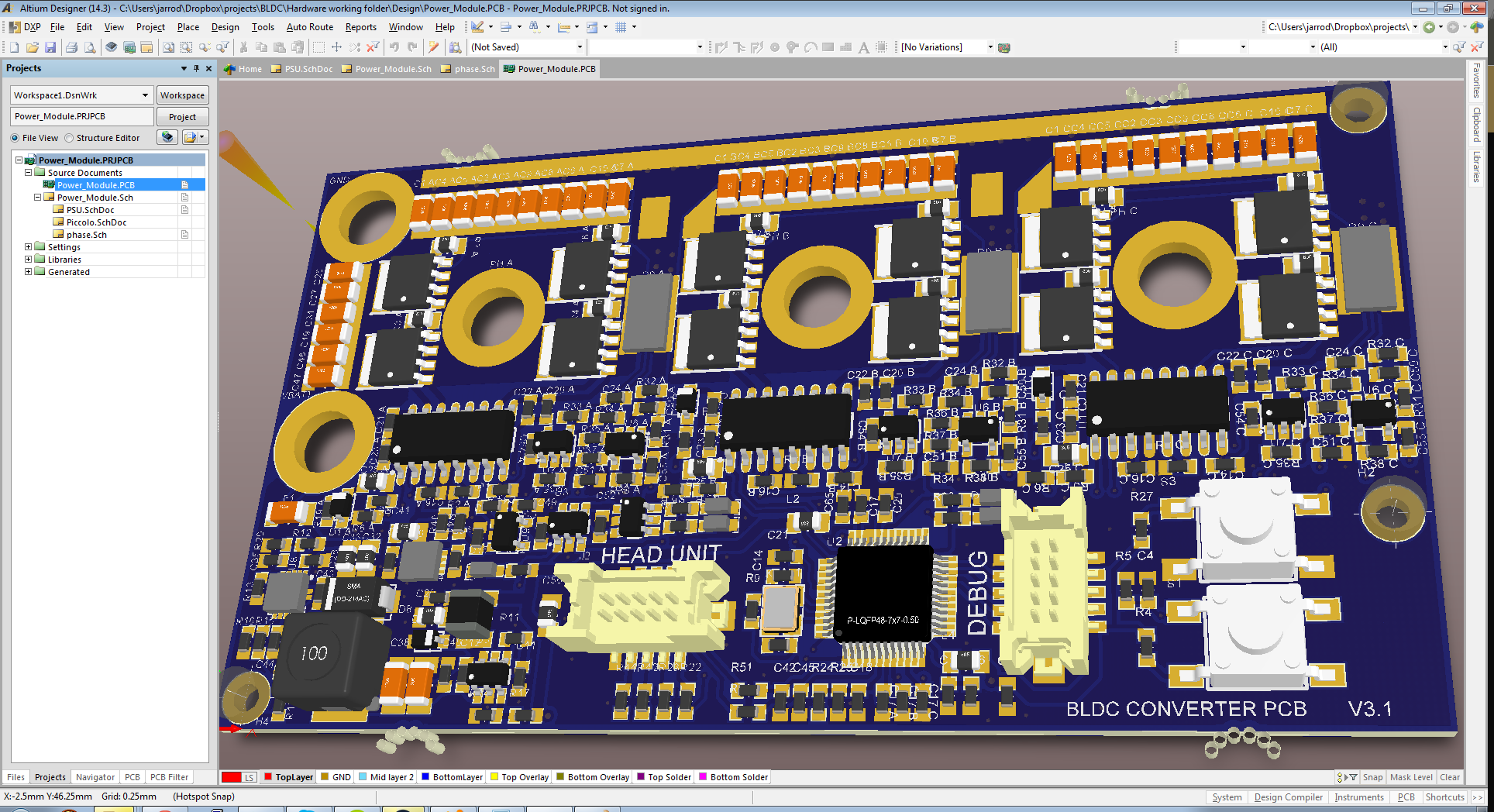
It's been some time since the last update for EverywhereElectric, but we have been working on it! After many hours pushing pixels in Altium, V3 of the PCB is ready!

I got bored one night and downloaded 3d files for all the components, it is actually very useful for things like connectors and odd components as you can verify footprints and clearance for component placement. And it looks freakin' awesome!
PDF schematic: https://www.dropbox.com/s/0rzs2lx15ip5onw/BLDC%20Schematic.PDF?dl=0
I've done a lot of work around the power supplies, as that was a big issue in the last revision which had startup and minimum load issues, also the 3.3v linear reg for the Piccolo chip would get uncomfortably hot regulating off the 10V rail. the new solution is to buck the battery voltage down to 10V for V_DRV, then run a 5V linear reg and 3.3V smps.
V_DRV (10V) needs to run the gate drives and all other power supplies including the head unit (I figure it's better to have just one rather expensive 60V buck in the system) so I chose a beefy 1.5A 60V buck from TI, the TPS54160. this should have enough grunt to run the phone charging circuit too. or if we decide to have a 60V reg in the head unit then a 0.5A version of this part is available. I'm running it at 850KHz to keep magnetics small.
The 5V line is just running opamps and the logic line in the gate drive chips, a 100mA LDO is used for this.
The 3.3V line needs a bit of current, it drives the piccolo uC which can draw 120mA, a switchmode is used to reduce power loss. I chose a little SOT26 buck from Alpha&Omega, AOZ1282 which I've used in other projects, very easy chip to use, fixed 450KHz makes magnetics tiny, it's good to 1.2A and 35V input.
I updated the connectors to SMD 1.25mm pitch Hirose parts, one for JTAG, one for the head unit/throttle/brake. they are locking (important on a bike!) and the female connector crimps on to stranded 26-32AWG wire. in the last revision we used 0.1" headers, but because they were surface mount (so the pcb can be heatsunk directly to a metal plate) they used a lot of space.
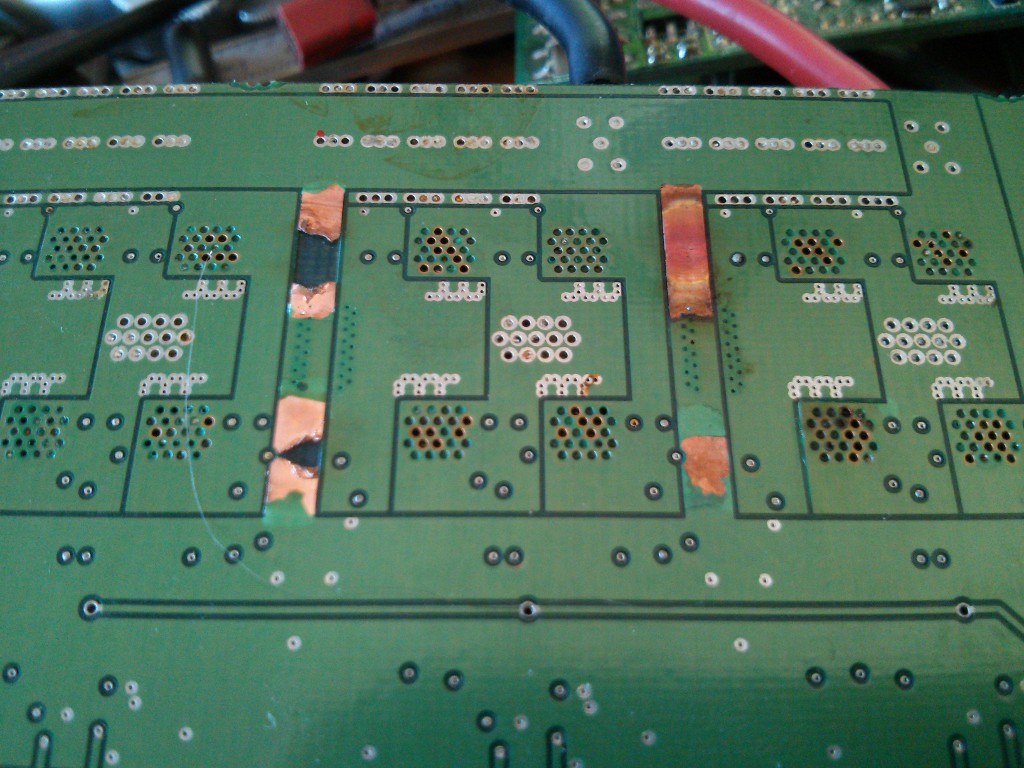
There were some pretty fundamental issues in the last rev which could have caused blowups, the first was a layout issue. as becomes apparent when looking at this catastrophic failure.

look at all those untented vias! Oh and the fused tracks too ;) The amount of current required to fuse those tracks only occurs if shoothrough of the FET's occurs, but it shows pretty clearly that significant current flows through those tracks running between the low-side shunt resistors and ground, which is also the ground reference for the current feedback opamp, so it would have had this extra V=IR voltage across it, who knows how that would mess with the field estimator algorithm.
To solve this potential issue, I've beefed up the ground return paths on multiple layers and used a star-ground configuration to separate the power and logic sides of the circuit and remove any strange voltage gradients across the ground plane.
Second issue was the over current protection, it worked via multiple comparators which pull the gate drive disable pin low when the current through any half-bridge exceeded the set limit. the problem is that it would re-enable the drive as soon as the current fell. so this would have caused oscillation and each time it all goes overcurrent, the fets become undriven and potentially have diode conduction occurring, reverse recovery time could have caused some amount of shoothrough and shoothrough causes FET's to fuse short, and the image above to happen.
So we want to avoid uncontrolled disabling of the gate drive. I've implemented a bit of logic, first a comparator on each current sense line which detects overcurrent conditions, all these overcurrent signals are OR'd and drive the clock of a D-type flip-flop which disables the gate drive and pulls a pin on the uC low. once the uC sees an overcurrent condition has occurred, it can prepare for it and reset the gate drives by pulsing the reset line on the flip-flop.
A prototype PCB is on it's way now, next post should be assembly and testing!
 Jarrod
Discussions
Become a Hackaday.io Member
Create an account to leave a comment. Already have an account? Log In.