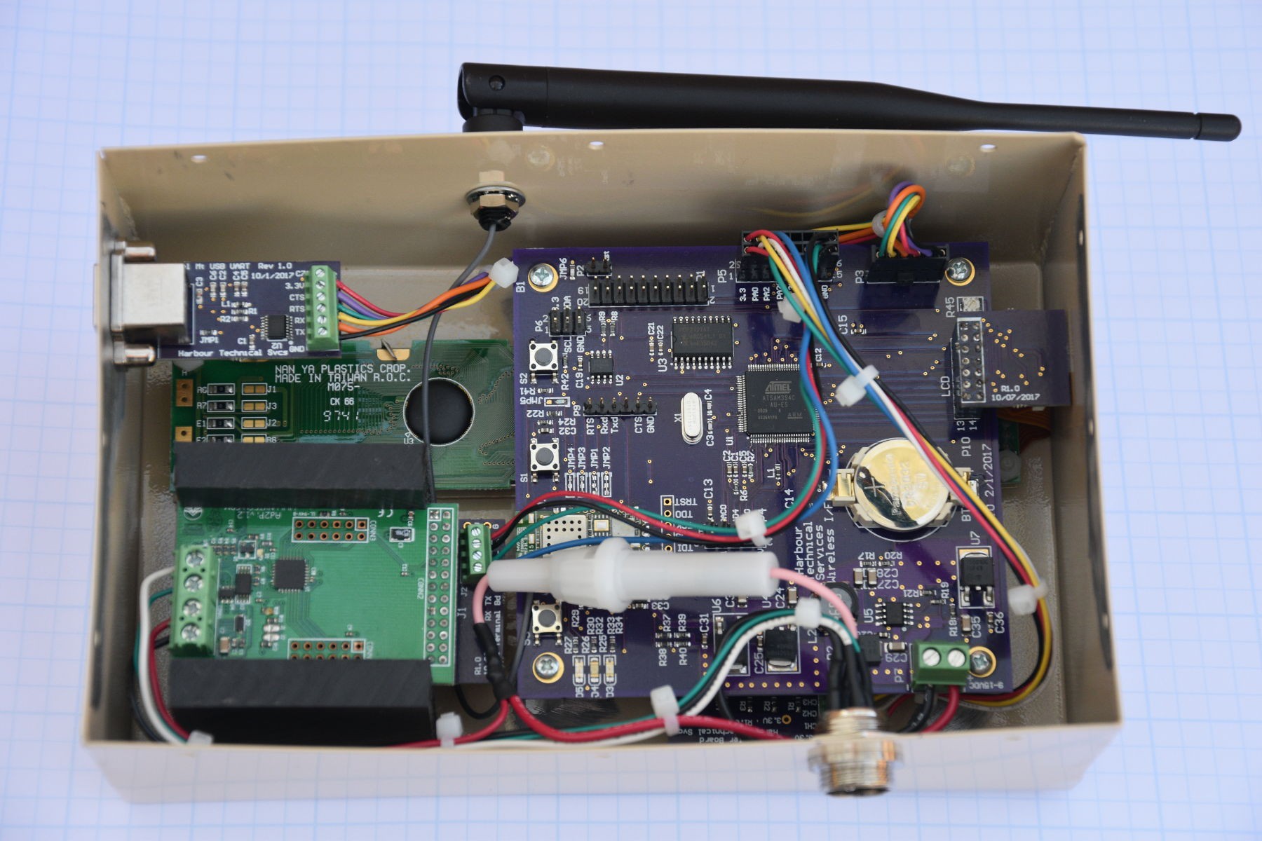
Completing the system required a few details. I needed a few toggle switches for the minimal user interaction, which needed ESD and EMI protection before feeding them into the microcontroller GPIO inputs. A simple board with RC filters for the EMI protection and TVS diodes for the ESD protection was designed and built. This board is buried under the main PCB and not visible in the pictures. The main PCB was designed to use a standard rectangular header to interface to the LCD display. I got a great deal on a box of LCD displays that already have a flat cable attached. Rather than remove the flat cable from the display, I made a small adapter board that goes from the .100 2 row rectangular header to the flat cable. This had the advantage of being a small, inexpensive board to check the new footprint of the flat cable connector. The adapter board is visible in the upper right corner of the box. Power and serial data come into the box on the 4 pin round connector at the bottom. A power fuse was added to protect the host system from possible faults in this box.

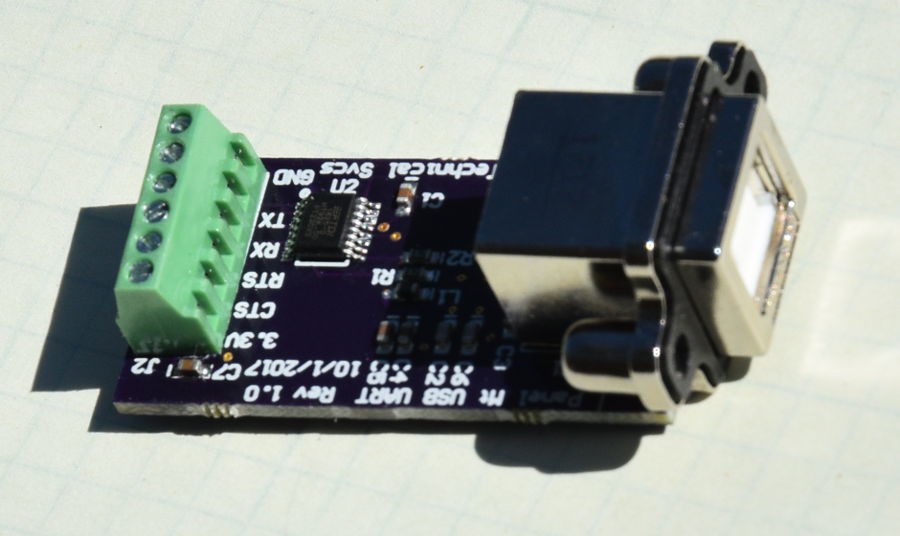
In the past, I have used RS232 level shifters and a 9 pin DSub connector for serial connections to projects like this. It seemed like a better idea to just make a small board with a chassis mount USB connector and a USB to serial chip on board. This would allow direct USB connection and skip the RS232 level shifters. Amphenol makes some really nice chassis mount USB connectors that worked perfectly for this. This module will replace the 9 pin DSub in the future on my projects.

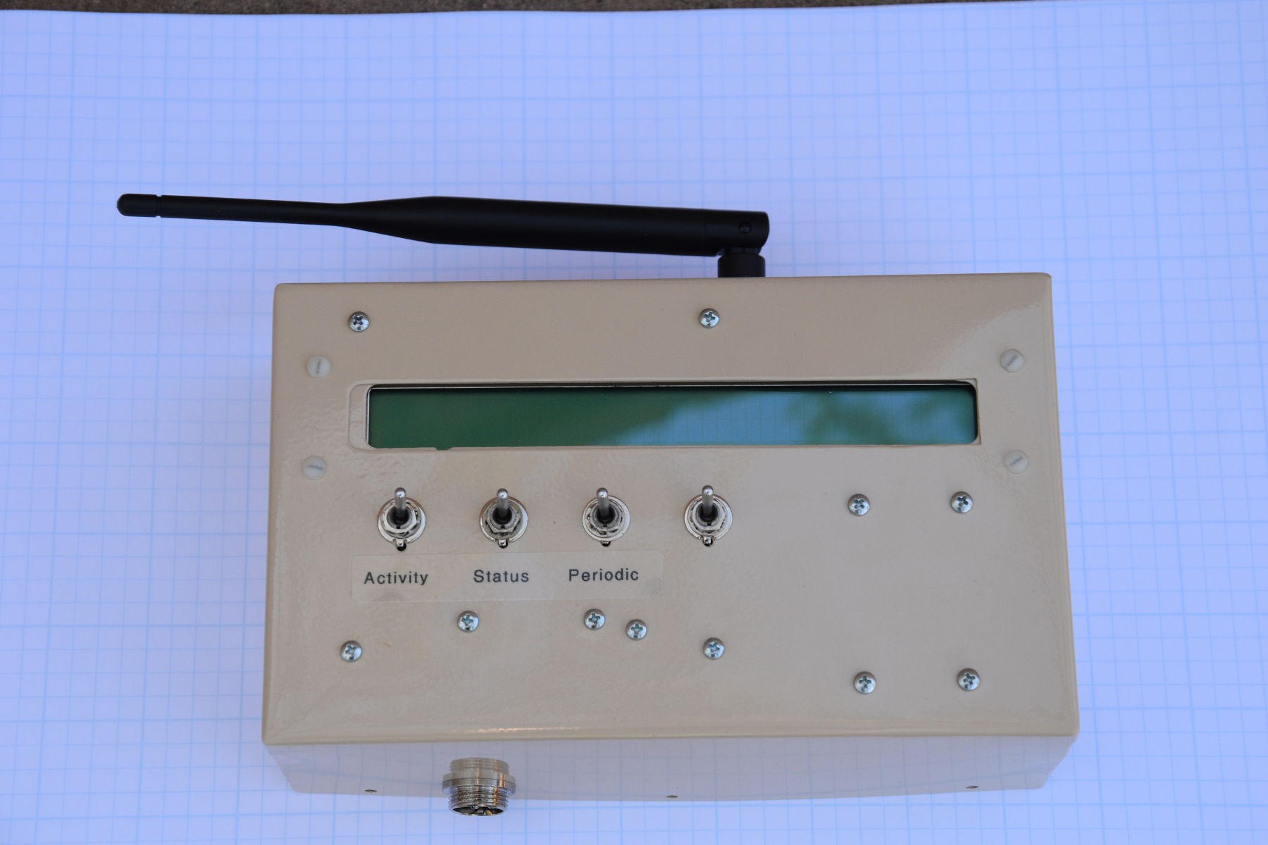
An aluminum case was built from 0.030" 5052 aluminum and powder coated. All the boards were installed and the system tested. A couple of quirks in the user interface code needed cleaning up, but it looks good now. A back plate that is not shown will allow mounting the box in the system.

 Bharbour
Discussions
Become a Hackaday.io Member
Create an account to leave a comment. Already have an account? Log In.