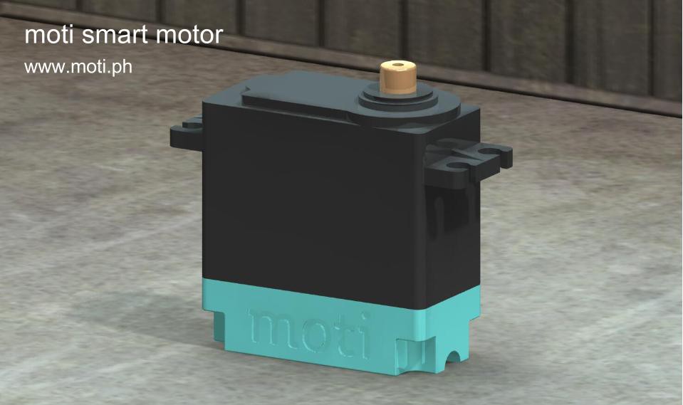
Here's a rendering of a fully assembled moti:

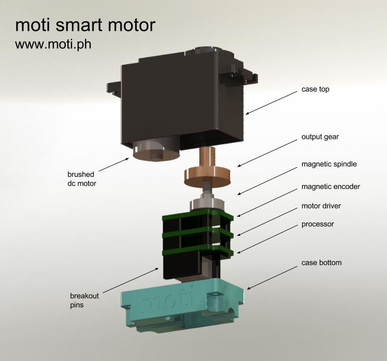
and here's an exploded view:

The exploded view shows how the product assembles together. You can see how the magnetic spindle has a shaft that fits in the output gear. It's the same size as the potentiometer shaft used used in conventional servos. The spindle spins right above the magnetic encoder IC which is on the bottom side of the pcb. The spindle maintains it's rotation axis by fitting a nipple (?) into a registration hole in the pcb. The design has changed a little since this model was generated but it's still quite close.
Drawings were done in Solidworks. The same designs are used to generate .stl files that have been used to 3d print the case bottom and the housing for the magnetic spindle.
 Nicholas Stedman
Discussions
Become a Hackaday.io Member
Create an account to leave a comment. Already have an account? Log In.
So if this is working, that is meaning we can use this Servo to built a robot without any other main controller?
Are you sure? yes | no
Are you sure? yes | no