 Matias N.
Last few weeks I've been working hard on this project and I now have a prototype built. Moreover, I have a firmware which demonstrates all the available functionality of the board: sensors, charging circuitry, screen, buttons, buzzer, etc. While there's still a lot of more features planned and polishing (mostly making the screens look nice and the user interface comfortable), I think that this is a good milestone.
The Build
When I designed the PCB I knew I would have to use a stencil since I was including some parts, such as the IMU, barometer and battery charger IC, that didn't have exposed pins but pads underneath. Moreover, these components are not particularly cheap so I didn't want to risk ruining them by reworking them if soldering went bad. So, together with the PCB, I ordered a stencil from JLCPCB and got some solder paste. This was the first time for me using this soldering process and to my surprise it worked really well in one attempt. You can see a video I put together from footage taken with my crappy digital microscope (someday I will upgrade it to get better image quality).
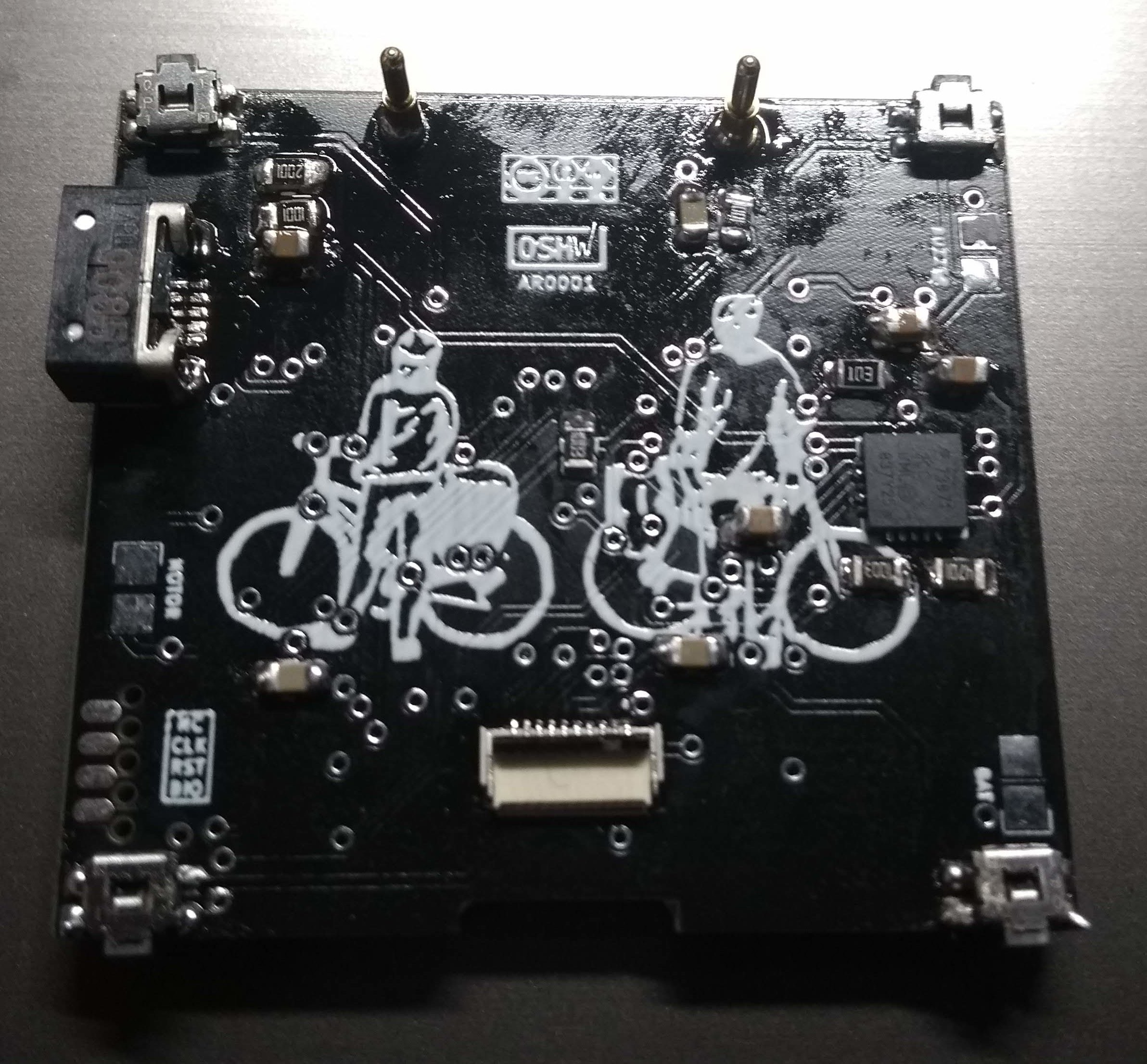
As you see, I placed difficult components on both sides, which was not the best idea. Next time I will only leave simple components which do not require a stencil on the bottom in order to facilitate mounting and soldering.
The resulting board (screen not plugged)
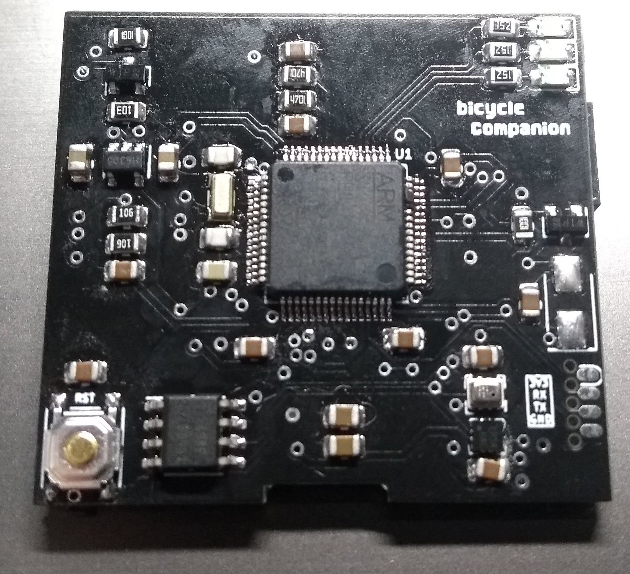
BTW: ignore the OSHW logo, this is not yet certified but I'm the process of doing so (need to finish the firmware).
Flashing/Debugging
For this board I decided to try out the SOICbite approach for flashing and debugging the board. This works by using a (modified) SOIC8 clamp with grabs to some pads on the edge of the PCB. In my case, this exposes 3.3V power, SWD and UART. I liked this idea since I didn't want big connectors increasing the size of the case I would use to enclose the PCB. In my experience with this approach so far I must say it is probably good for very small boards and for brief flashing/debugging periods. In my case I have the board clamped next to me all day and it is very easy for the teeth to lose contact with the PCB which leads to resets, SWD disconnections and UART errors. This is inevitable since I need to interact with the board by pushing buttons.
For this reason I decided to take advantage of the USB port and implement DFU flashing and serial communication by booting into ST's integrated USB bootloader and enabling the CDCACM device emulation in NuttX. I manage to have this working but I didn't have good results either. It seems that it easy to brick the board since the bootloader does not recognize communication errors easily. Moreover, software-based CDCACM emulation in NuttX is a bit brittle since whenever you reset the board (for example, to flash or debug it) my Linux computer gets really confused (I even managed to completely hang Linux this way).

I started a list to track all improvements for an eventual revision of the board: https://gitlab.com/bicycle-companion/hardware/-/issues/6
User interface
I already had a more or less functional code base when I built the first prototype based on a Nucleo L476RG board, however there was still lot to do with the real board. Mostly, I finished all the required interfaces to on board devices and exposed functionality via specific screens, for which I used LVGL (formerly LittleVGL).
The idea is that you can move using the two top buttons between a series of screens (last one being the settings screen). There is one "main" screen which is thought to be used while riding the bicicyle and contains most useful information there. You can then go into the other screens where each one focuses on one particular kind of information. This is the list of screens with its functionality so far:
- Clock screen: displays time and date, nothing more. This is designed to be updated at a frequency of one minute and used as "screensaver" when some time has passed after not detecting wheel motion. The MCU can go into low power mode, waking up only to update the time. Eventually (maybe after a few hours) it could be completely off but the screen would then not be updated. Every other screen updates at 1Hz.
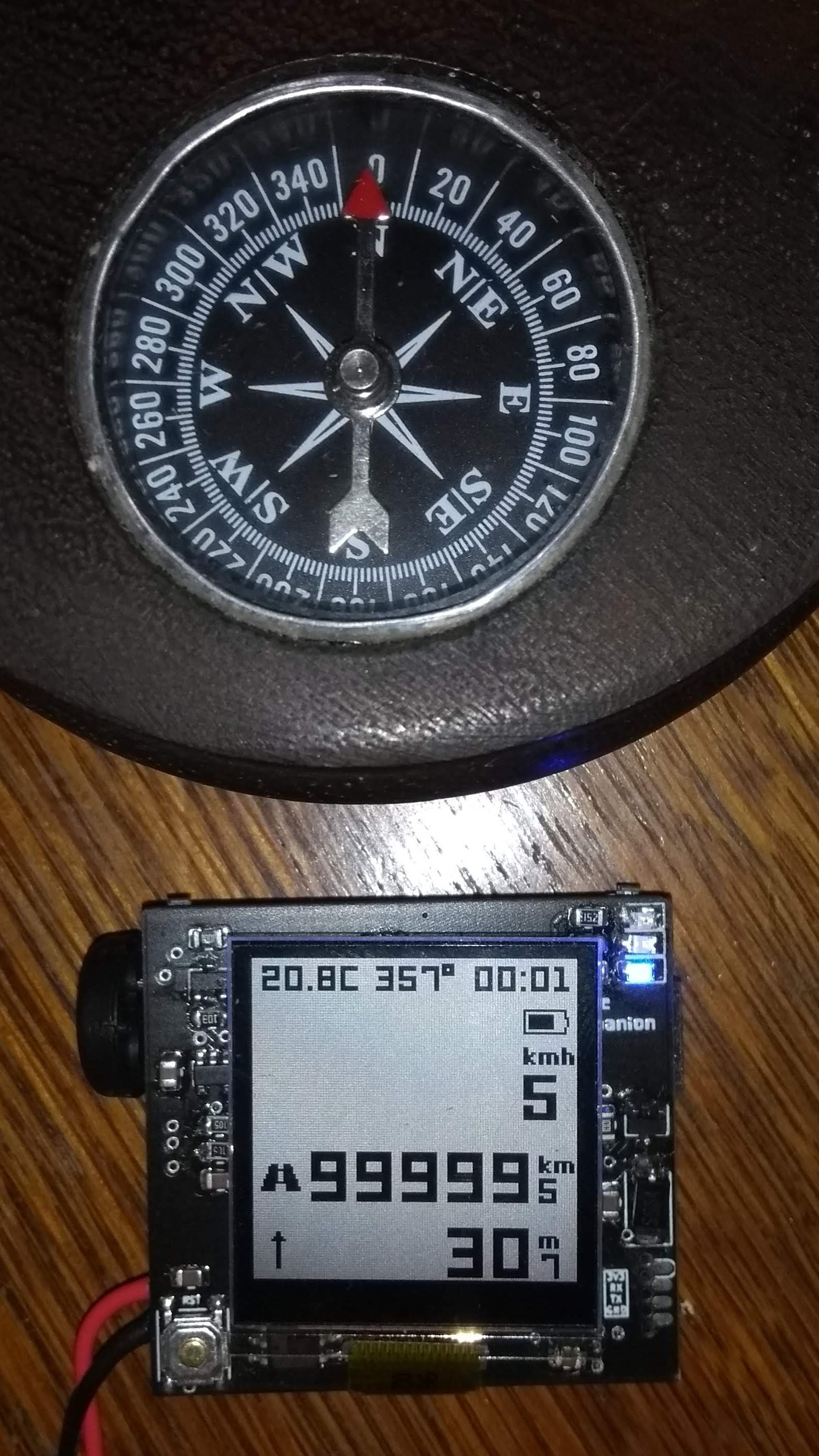
- Main (or "speed") screen: this screen shows: temperature, magnetic heading, time, speed (in big number), traveled distance, sea-level altitude and battery level indicator.
- Battery: since the big screen does not show detailed information regardy the battery state, this screen displays battery voltage, a charge-level (in percent), status (charging, discharging, etc) and an estimate of the remaining charge/discharge time.
- Temperature: current, historical minimum and maximum temperatures and a plot of the last 24hrs. The 128px resolution allows for 15min per pixel to be represented which I think is detailed enough.
- Compass: this screen displays a compass view, with a needle indicating compass direction and a middle window with exact heading in degrees. I used some of the widgets in LVGL for this and I must say it looks quite nice. Moreover, I was surprised of the precision of the magnetometer (once it is calibrated to removed soft-iron distortions). I'm also estimating roll/pitch from accelerometer in order to derotate magnetometer vector and provide accurate compass heading even when the board is not parallel to the ground. While for now I'm just taking one sample of the accelerometer (which assumes it is relatively still) it works surprisingly well. Of course when on the bike this might change, but this could be easily improved.
- Sunclock: this screen shows sunrise/sunset and sunlight time, according to the current location. This requires knowledge of GPS location and timezone. Right now this information is hardcoded but I will probably build a list of major cities in the world, each with its coordinate and nominal timezone. This is quite a bit of information but if I limit this to major cities and get get around 10k cities using available flash memory. I will work on this later though.
- Settings: right now it mostly serves to allow me to start magnetometer calibration but the idea is to be able to configure most things here. This will work with a system of menus and sub-menus.
As you see, some screens are just text printed with no effort in UI design. I will continue to work on that but I wanted to get the main functionality and set of screens done first.
Testing
There's still lots of testing to do. Right now I only managed to compare the compass heading with an actual compass and it seems to be very precise. The barometer also seems to be precise compared to my city weather information. The battery level is also precise compared to a multimeter.
One of the main things I would like to test is the speed/distance calculation, compared to my (dumb) bicycle computer. For this I will either need to build a mount or hack my existing one (sadly I didn't have the foresight to make it compatible). Since right now I don't have access to a 3D printer, it seems I will have to rig something up for this test.
Finally, one of the most important aspects to me is to test the low-power aspect of this design. There's still a lot of things to tweak but as I selected low-power components and considered this in the design I would like to verify some power use numbers for sensors and for the MCU during sleep modes.
HackadayPrize
As you may have noticed, this project is submitted to the hackaday prize. Right now the community vote is open so if you like this project, please click "Like" on the project page. Moreover, if you have any comments, please let me know (or feel free to open issues on the GitLab page to discuss ideas for possible features I might add to the firmware or to an eventual second revision of the board).
Discussions
Become a Hackaday.io Member
Create an account to leave a comment. Already have an account? Log In.