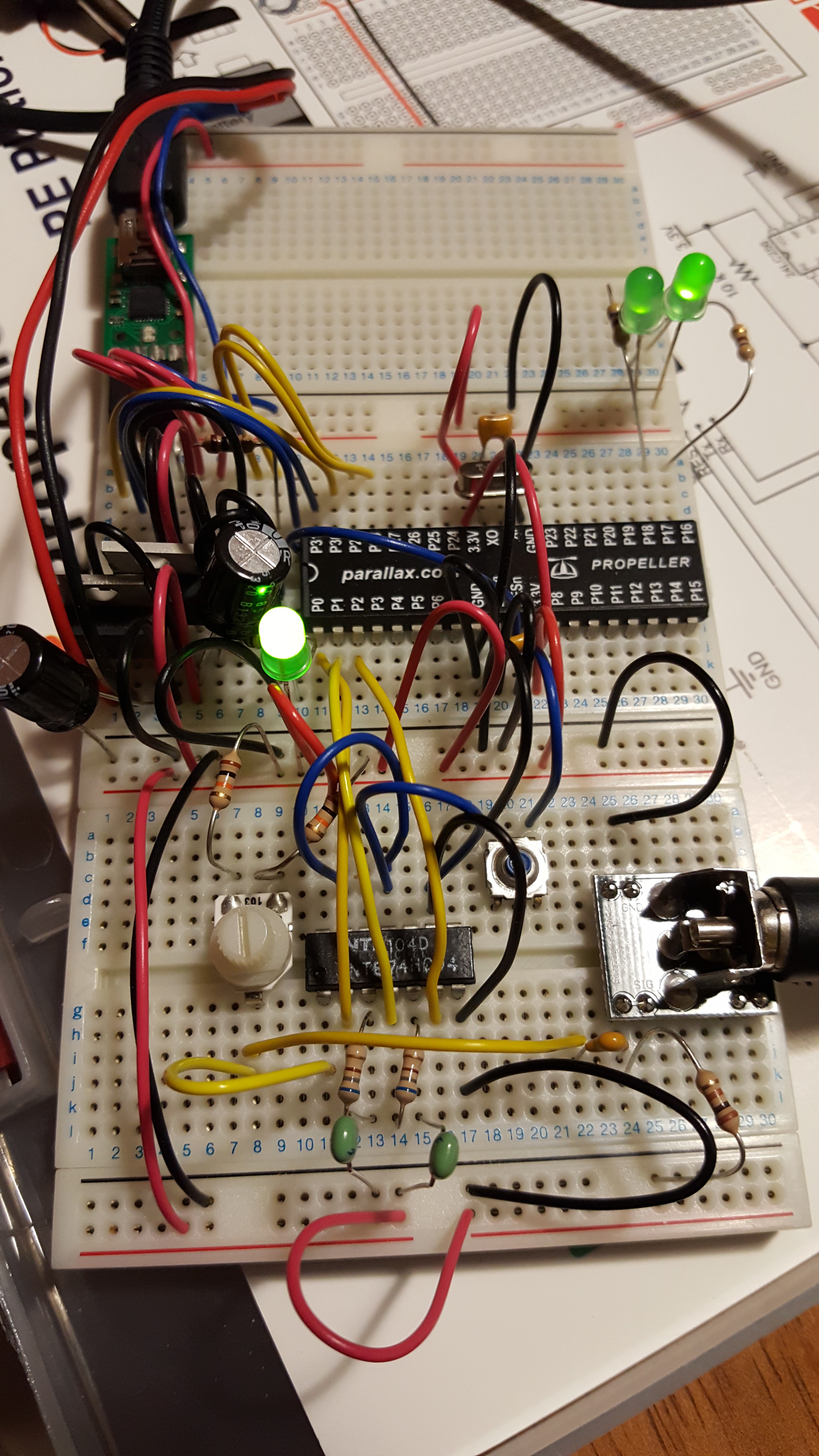
I started out with the Propeller Education Kit. I added an RCA breadboard converter that I got from Parallax a while ago while working on Propeddle and L-Star (I don't think they carry the RCA plug breadboard converters anymore, that's a shame. But they still have the PE kit I think, and they just announced the new Propeller FLiP which makes breadboarding even easier).
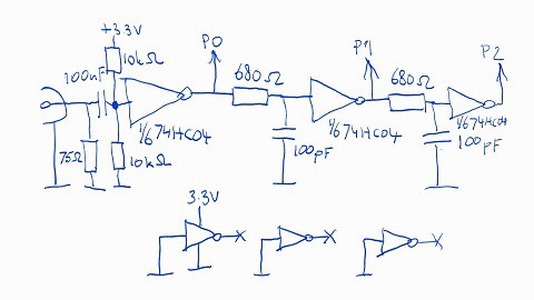
I also added a small circuit based on a schematic that I found online:

The S/PDIF (coax) input signal is an unbalanced signal with about 0.5V peak-to-peak. It's terminated with a 75 ohm resistor conforming to the standard (75 ohm input impedance; note: the photo shows a 100 ohm resistor, that worked fine too). Then the signal goes through a capacitor which acts as a DC decoupler. Then the signal is pulled halfway between the positive and negative supply voltage of a 74HC04 inverter port using a voltage divider made of two 10K resistors (the photo at the top shows a potentiometer to adjust the input voltage but this turned out to be unnecessary). The first inverter acts as an inverting amplifier to digitize the signal so it can go into the Propeller.
The two inverters that follow, with the R/C networks at their inputs, generate delayed versions of the signal at P0. I didn't run the numbers and I don't want to connect my oscilloscope to verify it (it's buried in the garage), but my source tells me the each of the ports-with-RC-circuits (between P0 and P1, and between P1 and P2) generates a 60ns delay, so a total of about 120ns.
The highest frequency input that we want to accept is based on a 48kHz sample frequency. That means in the worst-case scenario, there are 48000 full frames of data per second on the input. Each frame is 2 subframes and each subframe is 32 bits so that's 48000 * 32 * 2 bits per second, that's a clock frequency of 3.072MHz. Since there can be up to two biphase bits per data bit, the minimum length of one biphase pulse may only be 162.7 ns (give or take, with jitter).
So the delay is shorter than the shortest bit time, and that's important. By performing an XOR on the original input and its delayed version, you can get a signal that represents each flank in the original signal by a short pulse. This takes away a big problem with the decoding: in S/PDIF the level of the signal is irrelevant, but the Propeller has to know what the state of the signal is in order to wait for it to change. By XOR'ing the signal and its delayed (noninverted) version (and by keeping the delay under the length of the shortest expected input pulse length of 162ns), the signal that the software would have to deal with, is always LOW when the S/PDIF signal stays the same, and HIGH for 120ns when the input signal changes.

During one bit clock of the original signal, two pulses can be seen on the output of the XOR for each "1" bit, and one pulse can be seen for each "0" bit. During preambles, the signal stays the same for 3 biphase bit periods so we won't see any pulses for longer than that.
I ran a couple of tests with this, and tried to put some assembly code together to verify (sort of) that this was a usable concept.
First I wrote a short PASM program to light up one LED when the signal was high and another LED when the signal was low. On an S/PDIF signal that was basically digital silence, the LEDS were equally bright, as expected.
Then I wrote a short PASM program to test pins 0 and 2 at the same time, using the "TEST maskP2P0, INA WC" instruction where maskP2P0 was set to %101. This tests whether pins 0 and 2 are high, and sets the carry flag if the parity of the result is odd. In other words: it tests whether either pin 0 is low and pin 2 is high, or pin 0 is high and pin 2 is low (basically an XOR function). I then used the MUXC and MUXNC instructions to make one LED light up when the carry flag was set, and the other one when the carry flag was cleared. It was clear to see that one of the LEDs was brighter than the other.
So that works! But now... How to write a program that's fast enough to recover the clock and detect preambles?
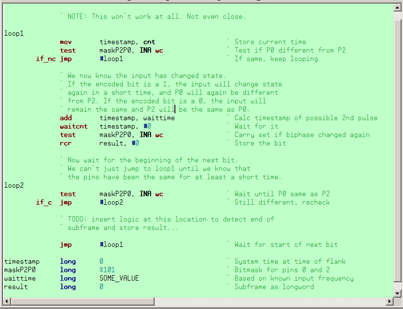
This is a problem, because the signal changes so fast that the Propeller can't keep up with just Assembly instructions. A simple program like this is not going to work:

The code waits for P2 to be different from P0 (meaning the input changed from low to high or from high to low). It saves a timestamp from when it detects the change.
So the timestamp now represents the time at the beginning of the data bit. To find out whether the data bit is 0 or 1, it waits for a certain time (the middle of the data bit) and tests if there was another change to the input signal. If there was, P0 and P2 are different again and the carry is set. It rotates the carry into the result from the top, so in the end, the first bit is at the lsb of the result
Finally, it waits until P0 and P2 are the same, before it goes back to the first loop again. I left out the code that tests for a preamble and stores the result if it sees one.
There are so many reasons why this won't work, and there's no hope of getting this to work either:
- To start with, this seemingly simple loop is spectacularly slow compared to 48kHz S/PDIF. Remember the time from the start of a data bit to the middle of a data bit is only 162 nanoseconds, and the Propeller takes 50ns to execute most of these instructions. That means by the time it detects that P0 and P2 are different in the first loop, the half bit time is already almost over!
- The three instructions that are needed to save the time stamp and check if P0 and P2 are the same, are incredibly jittery. Ideally, the Propeller would generate a timestamp itself but this is impossible. The Propeller has instructions that can be used to wait until the input pins match (or don't match) a pattern but those are also unusable because it would need to check for two patterns: P0 high and P2 low, or P0 low and P2 high.
- There's no code yet to check for preamble, and the fixed value for the waiting time makes it necessary to precalculate everything. That's not what we want: the system should be able to deal with different input frequencies without interference from the user (or even reprogramming the chip with different time constants).
- Sure, there is some space for optimization (for example, by folding the loop and putting the outer jump just before the waitcnt instruction, it would waste less time), but there's no way that this will ever be fast enough to do its work in (essentially) 2 * 162 = 324ns (less than 7 instructions). And once again, there's still no code in there to check for preamble, out of sync and frequency mismatch.
I thought of adding a hardware XOR port so I could use the waitpe / waitpne instructions to wait for each change. But even then, the code has too much work to do to get done in time.
So should I just add one or two external monoflops to recover the bit clock and maybe even detect preambles? But that seems like cheating: preferably I want to be able to even get rid of the 74HC04 and just make it work with some passive components. Adding monoflops is plan B, at best.
I also thought of letting cogs work in parallel. One cog waits for the high pulses during the first frame, one cog waits for the low pulses during the first frame. During the second frame, two other cogs do the same thing while the first two cogs transfer their work to the hub, and a fifth cog puts all the data together. But this is going to be massively complicated and then I still have to figure out how to detect preambles and synchronize all the cogs.
Then I looked into the possibilty of using the timers. It will still be complicated, but it might just work. More about this in the next project log. Jac Goudsmit
Discussions
Become a Hackaday.io Member
Create an account to leave a comment. Already have an account? Log In.