 Hebrewhammer130
This is a detailed examination of the components of the hand cycle. I found the RPM sensor to be in functional condition. The tensioning strap was in good physical condition. There was very little play in the hand crank and fly wheel bearings. I used my digital multimeter to assess the functionality of the RPM sensor and determined that once every rotation the sensor will momentarily ground itself and the rest of the time it will be open. The original hand cycle had a display that broke off several years ago. It never functioned properly but was suppose to display pulse rate, time, distance, speed and calories. Ideally the placement of the Android display would fit where the previous one was located.
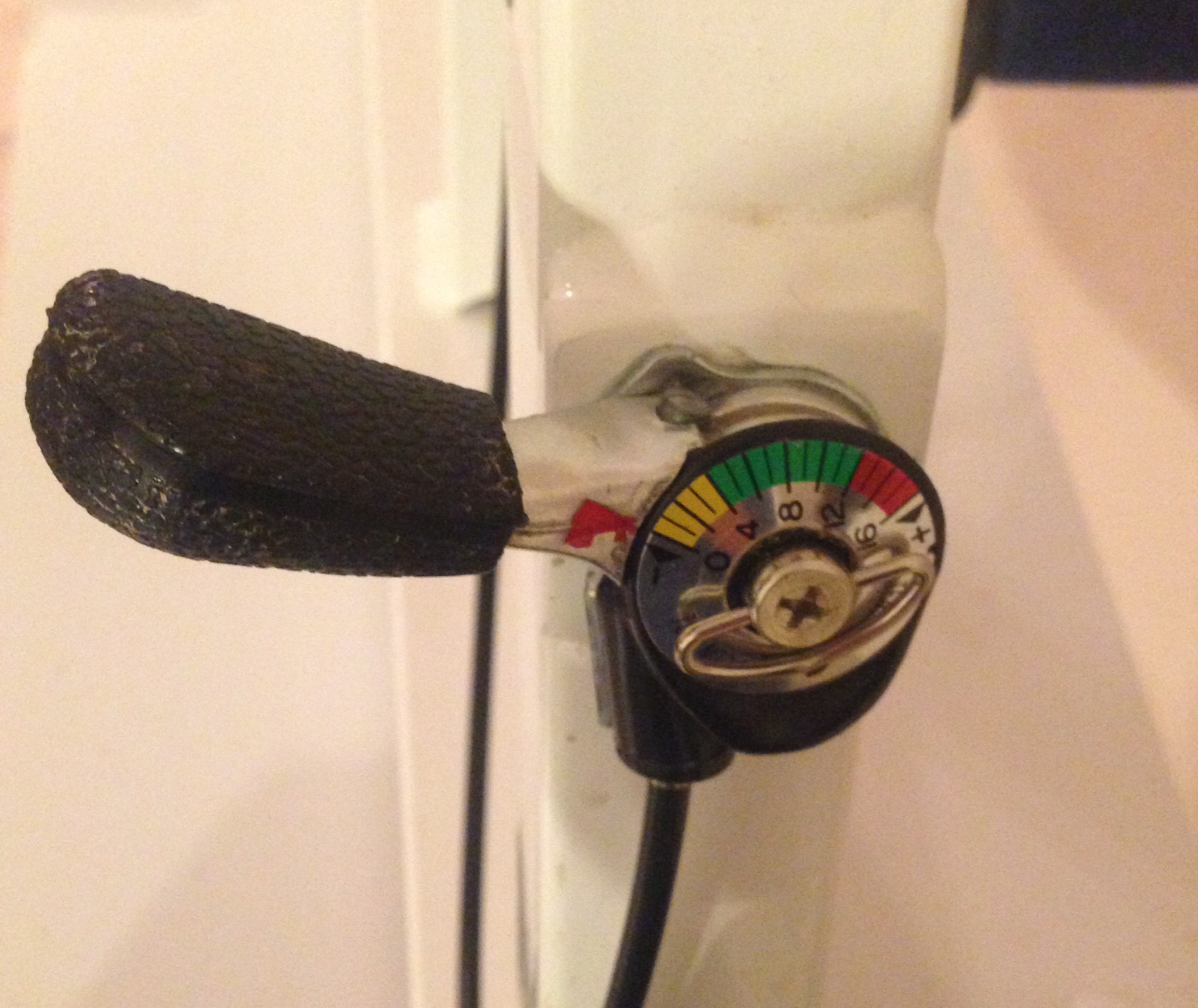
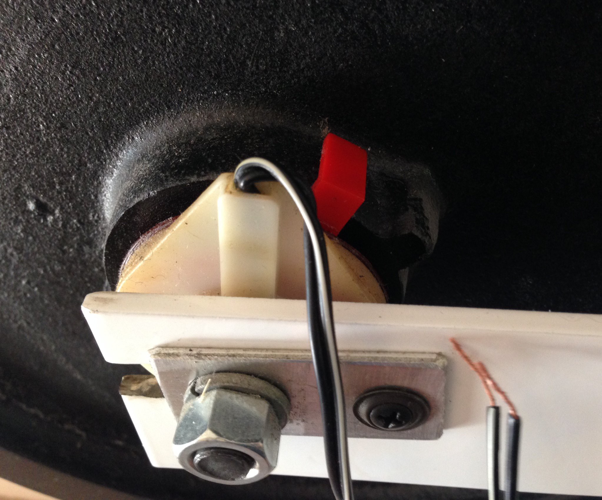
The above image is the tensioning mechanism for the hand cycle. Below is the RPM sensor in verified working condition.
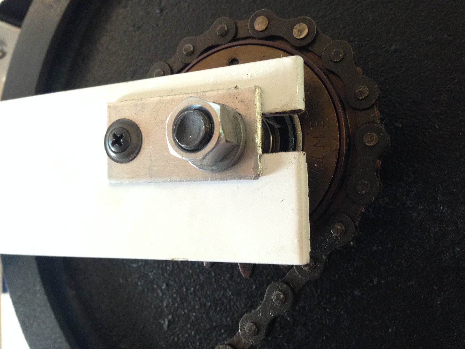
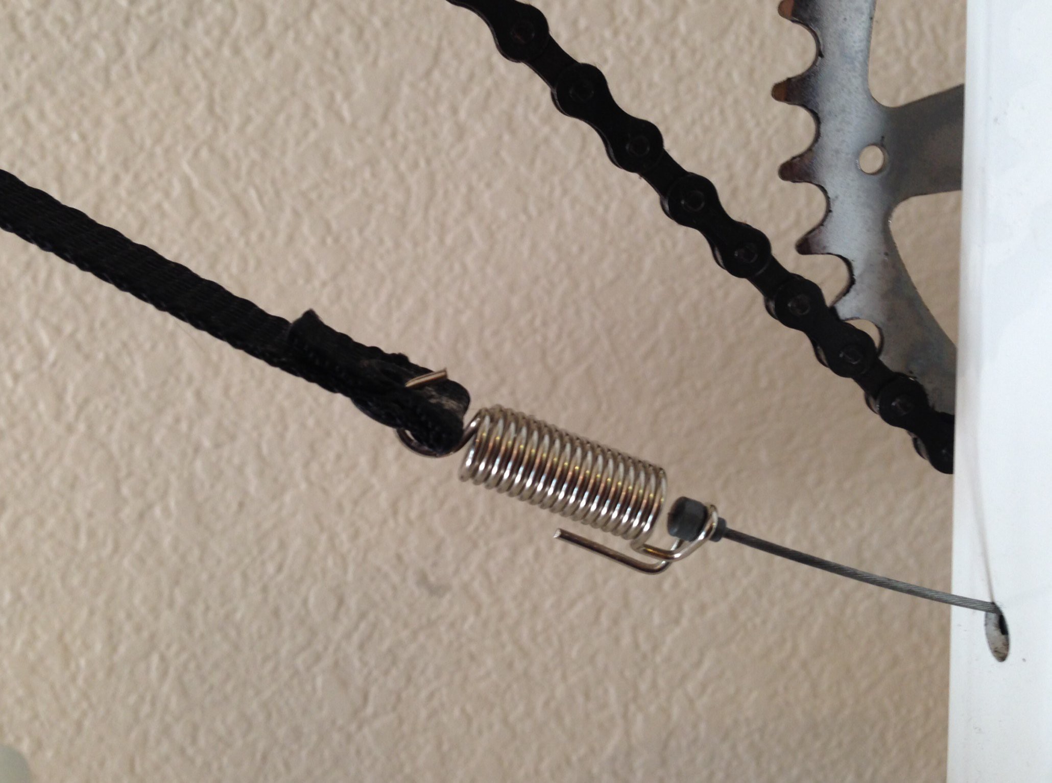
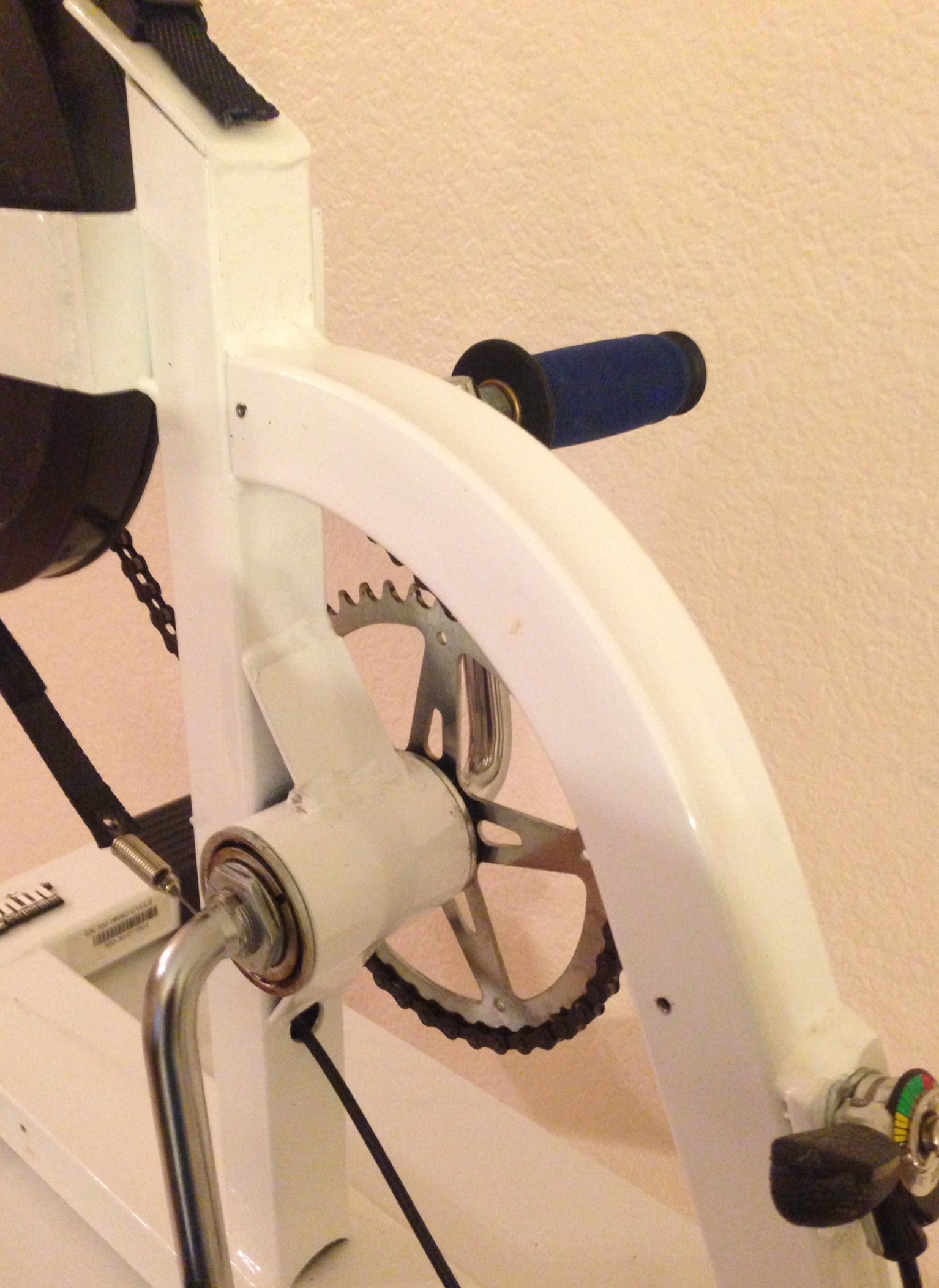
The above photograph shows the sprocket and chain assembly on the hand cycle. The image below shows the spring used to connect the tensioning strap to the adjustable mechanical tensioner.
 The image above shows the support frame for the hand cycle. The placement of the Android display will be in the upper left hand corner at the end of the tensioning strap.
Discussions
Become a Hackaday.io Member
Create an account to leave a comment. Already have an account? Log In.