 Bud Bennett
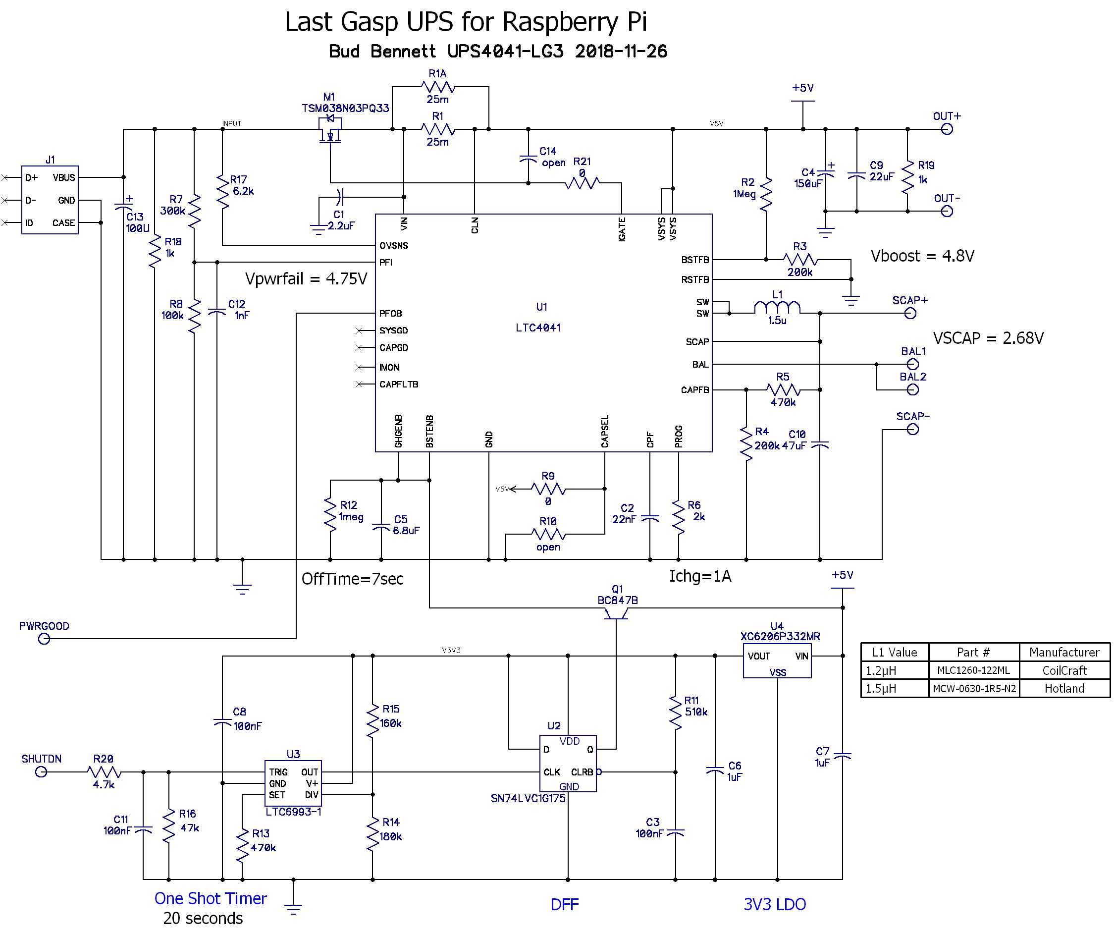 After an exchange of ideas with Analog Devices I have decided to apply a bunch of band-aids to try to fix the observed problems with the earlier versions. This design includes the RC filtering on the SHUTDN input, the RC filtering on the PFI pin, resistor loads at the input and output, and three modifications that deserve a bit more explanation.
Analog devices suggested the addition of an RC filter on the gate of M1, to reduce the inrush current when the input switch is turned on. The gate capacitance of M1 is already 2.5nF, so making R21 4MegΩ would slow down the switching time by about 4x. Increasing C14 to 7.5nF and setting R21 = 1MegΩ would have the same effect. I'm a bit leery of unintended consequences that may show up due to the slower turn-off time of M1, so this approach would probably be my last resort.
I added C13 at the input to help hold the input up when the input switch is closed. This may cause problems with the power fail comparator glitching after the input power is removed, but C13 can be removed if it worsens that issue. C13 is a tantalum, which should minimize voltage transients due to hot plugging the adapter.
Lastly, I reduced C2 from 220nF to 22nF. This reduces the minimum backup time from 500ms to 50ms. The reasoning behind this is to prevent prolonged relaxation oscillation by shortening the time between the input switch connections. If the output cap voltage is not allowed to fall completely back to zero then maybe after a few input cycles the oscillation will be broken. The success of this approach depends on the speed of recovery of the power fail comparator.
One more thing. I ordered a smaller inductor -- Hotland MCW-0630-1R5-N2. This new 1.5µH inductor is roughly 6.6x7x3 mm vs. 12x12x6 mm of the 1.2µH Coilcraft. The new induction is rated at 9A, which should be good enough for any intended load. The layout will accommodate either inductor.
New PCBs are on order.
Discussions
Become a Hackaday.io Member
Create an account to leave a comment. Already have an account? Log In.