 Bud Bennett
I received the LG4 PCBs last week. There was no point in assembling them since I did not have the PIC10F202 micro controllers, which arrived yesterday. I was able to program the PICs (with my new PICKit4 programmer) and populated the PCBs today. So far so good. On the bench, the circuit performs as expected; and initial testing with a Raspberry Pi2B and ZeroW are ongoing.
Yes, there is a solder bridge from SCAP- to C8, but it does no harm so I let it remain.
The relaxation oscillation problem from previous passes doesn't show up on this pass. I tried a couple different AC adapters without any issues. Reducing C2 to 22nF appears to have fixed it.
The PIC is performing its function as designed. I triggered the SHUTDN pin and timed out the oneshot and the off timer -- both were close to nominal design targets. There were no issues with the reapplication of power.
After verifying basic functionality, I attached a 4Ω load and a 100F supercap. I let the supercap charge to full (2.67V) and pulled the AC adapter out of the wall. Here's the resulting waveforms at the output and the supercap:
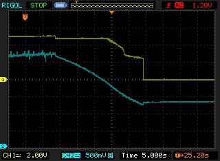
As expected, the 100F cap could not hold up the 1.2A load for very long -- not long enough to allow the older/slower Raspberry Pi variants to shutdown safely (but they also don't draw anywhere near this kind of current drain).
I swapped out the 100F with a 400F and repeated the test:
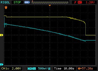
The 400F supercap provided 1.2A @ 4.81V for 80 seconds.
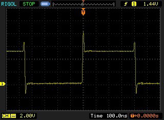
This is what the SW node looks like when charging:
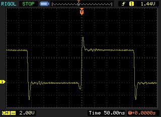
and boosting to a 4Ω load:
There was no bandwidth limiting on my 100MHz scope. The switching waveforms don't have too much ringing.
Raspberry Pi Testing:
The Pi2B with the 400F supercap in the UPS is running without issues. I haven't seen any unexpected operation, but testing has been limited. I'm going to let the Pi2B/UPS combination run for a couple of days to make sure there are no spurious shutdowns or Pi hangups.
After that the ZeroW will get tested with the 100F supercap.
Almost finished...
Discussions
Become a Hackaday.io Member
Create an account to leave a comment. Already have an account? Log In.