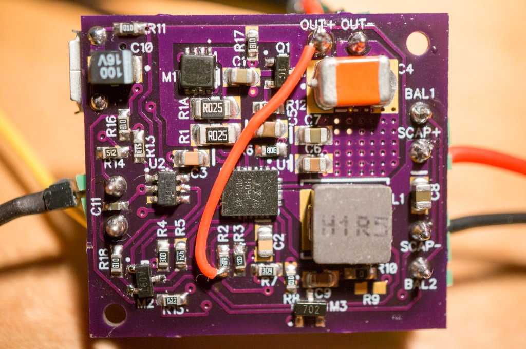
I populated one of the three PCBs received from OSH Park a couple of days ago. It is configured for a single supercap. I had to remove the LTC4041, PIC, and M1 from an LG4 PCB to avoid having to buy/reprogram a component for the new PCB. There was a problem with a trace on the LG5 PCB and I had to add a 30AWG wire to correct it. Final board looks like this:

I've contacted OSH Park about the problem...they refunded the order. But with my ugly fix the board is working as expected. I have tested the UPS with three versions of the Raspberry Pi: RPiZW, RPi2B and RPi1B. The same code works well for all of the tested Raspberry Pi variants. The new code allows the final SCAP voltage to drop to 2.3V (for a single supercap). I found that the SCAP voltage at the end of the shutdown sequence was within a few tens of mV from 2.3V. I left the target SCAP voltage with 2 supercaps at 2.4V since the rate of change is a lot higher when using two smaller supercaps -- a bit of margin to error.
In any case, the UPS is working better in all respects and I'm ready to call it a day and complete this project once again.
 Bud Bennett
Discussions
Become a Hackaday.io Member
Create an account to leave a comment. Already have an account? Log In.