The first and only version of Yapolamp to have been released into service with a child so far (Beta, or V1) stopped working at the end of last year and when I opened it up, I found it was still somehow pumping current round the LEDs without being able to store any energy in the inductor. Because the inductor had fallen off inside the enclosure. My confabulation is logged here.
Now, the new PCBs are in, for what I hope will be the next version in the wild. About the only things which are the same about this version, compared to Beta, are the LEDs and the fact it uses electricity to make it go. I will admit up front that this is one of the worst PCBs I have designed. It looks fantastic in matt black silkscreen but boy have I missed some traces. The first thing I noticed was when I fired up Kicad to print a schematic for component placing and I had a quick look at the PCB layout. There were air wires! How?! There's no way I would have knowingly sent this to the fab unfinished. Then I remember trying to make some changes and I must have got distracted, failed to refresh things and then ended up with unconnected sections.

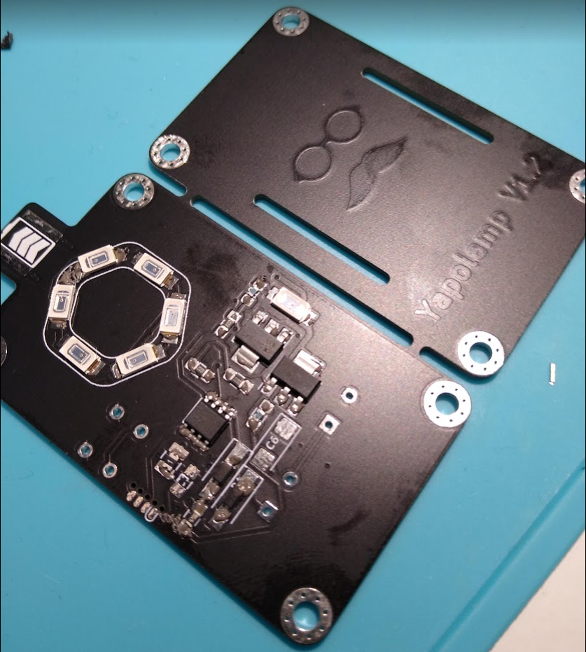
Thin and pasty. And a bit out of focus. The graphic homage to the project's namesake looks great on the back plate, with copper under matt black solder mask, and is hopefully subtle enough to spare him any blushes.
I initially soldered it up with some chipquik low temp solder paste and a hot air tool, following around after with more paste and the soldering iron where I had managed to fluff small passives up etc. Then I got brave and added the super capacitors. These things are hefty - marketed as 30F but the insulation round the outside says 44F... I also addressed the airwires I could see needed a greenwire. Even though I will have to revise this PCB and throw it away, it looks so nice I even went to the trouble of trying to colour coordinate my greenwires with it. Then I tried to flash a program and bingo, the chip confirmed it was programmed. Then nothing happened.

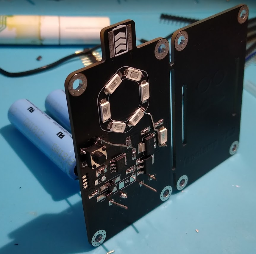
Supercaps go in here. Well they would go in a bit further and then bend their leads so the cylinders are flat against the back of the PCB but I had a hunch that I would need to keep some spare lead on these caps for reuse in a fixed revision.
Of course it did - these super capacitors are at 0V right now. So I set up with the power supply current limit on and tried to charge at the expected 500mA but the overcurrent protection kept kicking in. At 800mA (my diodes are rated for max 1A between them) I was still tripping the protection and I stopped. I had to change resistor values twice before I got anything under 500mA. This was around 260mA and I'm leaving this first build like that for now. It took a couple of minutes from memory to charge from 1V to 4.88V. Not bad but could be better. We can play with resistor values later.
Sadly, the presence of 4.88V in the bank didn't cause photons to start flying, so I went back to Kicad and looked for the next mistake - no joy. Then I spied it - a trace from one net was driving straight over a pad from another net. How had I parted with money to make this junk?! But still no joy. I wanted to check I wasn't being let down in the code, so I uploaded a really simple 10 us pulse every 100 ms, BUT STILL NO LIGHTS!
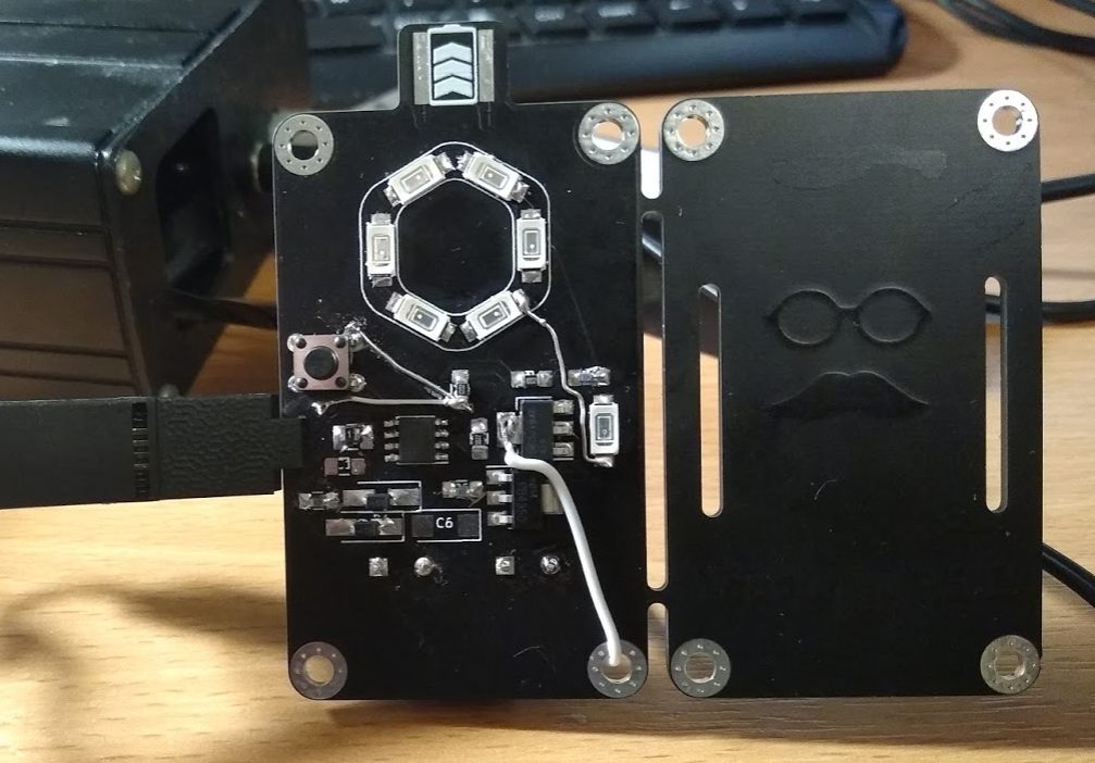
So I started probing for continuity on the board. At this point I knew my copper was a mess and I might get lucky and find out where. And when I flipped the board over and probed the inductor, I found that it was not connected to the MOSFET! WHAAAAAAT? One more greenwire to the rescue and bingo, photons leaked out into the room.

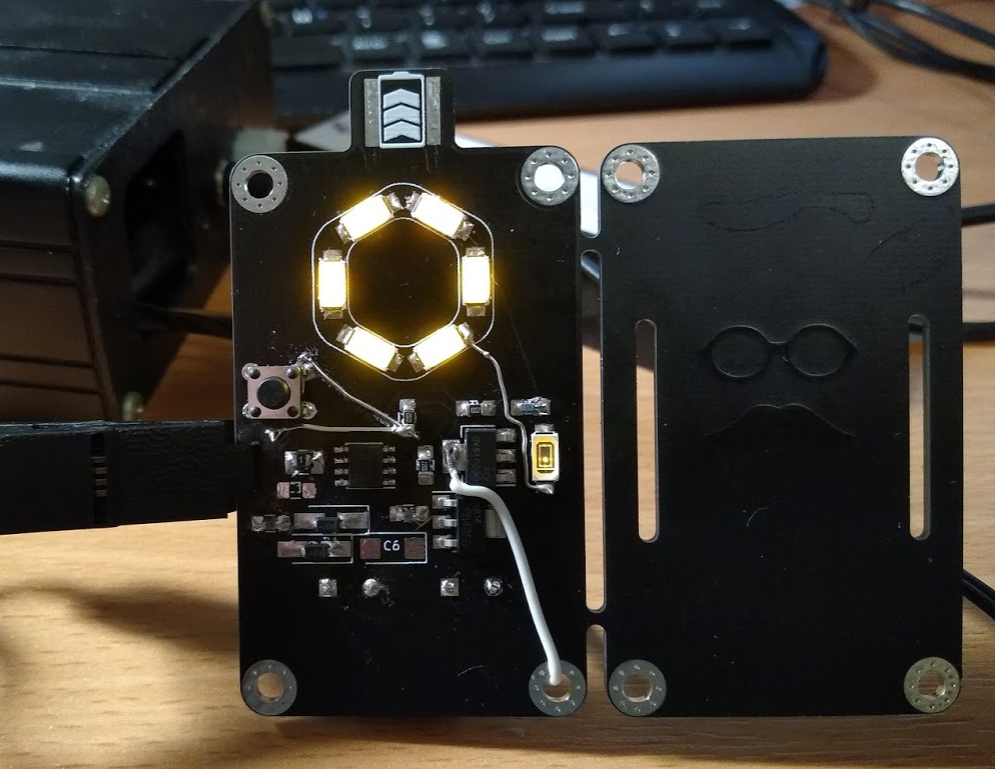
Photons leaking out slowly. This is the "always on" mode. For contrast, compare the ring of six "always on" LEDs with the "off" one that I use to drop the voltage into my feedback pin that triggers the next cycle of charging the inductor.

And, with the push of a tactile momentary switch, we are in "full on" mode. Notice the voltage dropper LED middle right is now on too, as it's only needed in this mode.
Apart from the blunders I have majored on above, there are a few other takeaways from this revision:
- The finish looks great. Will definitely use this scheme again
- The #SOICbite Programming/Debug Connector Footprint is doing grand as my UPDI connector. Although I have realised that if I have the ATtiny402 powered separately, say from it's supercapacitors, at the correct voltage, there's no need for me to break out VCC to the #SOICbite Programming/Debug Connector Footprint connector pads, right at the edge, leaving only GND and UPDI. That makes things simpler and perhaps safer when it comes to encasing it (probably a stacked assembly).
- I need to reconsider the switch placement - I had wanted to have the choice to reverse mount it and activate it by squeezing from behind the two plates together. But it's not far enough towards the edge and clashes with the supercapacitors.
- Safety fans will be pleased to hear there's a PTC fuse in this design between the supercapacitor VCC and the inductor/MOSFET route to GND.
I am ashamed to have made this many errors on one small PCB but I thought that on balance, it might encourage someone else who's having a bad day with their project. Just hope I haven't embarrassed @Ted Yapo too much with the association with this project! I will probably have a little bit more of a play test with this PCB before I revise and get another one made in the not-to-distant future, as there are bound to be more learning opportunities to be had before committing copper to FR4.
 Simon Merrett
Discussions
Become a Hackaday.io Member
Create an account to leave a comment. Already have an account? Log In.
"marketed as 30F but the insulation round the outside says 44F"... that's a bit worrying!
Are you sure? yes | no
Maybe for some applications but I'm quite happy if I get 50% extra capacity for free! I'm sure a test charge with the Joulescope will confirm the actual capacity.
Are you sure? yes | no
Oooh... Joulescope looks like a nice piece of kit.
Are you sure? yes | no
@Alan Green it's great - hasn't left my desk since it arrived! It's one of those things that has a great balance of performance and convenience/usability. The support from Matt Liberty is phenomenal, too. If you look at the response times on the forum you have to wonder if the guy ever sleeps.
Are you sure? yes | no
That's what I like about this community: even major botch jobs are presented with all the information what went wrong and how it was fixed!
Glad you got it working after all!
Are you sure? yes | no
Thanks - now it is working, I'm delighted to find that the code is driving it just as well as the dev board and breadboard version.
Are you sure? yes | no