So last log we looked at the pulse durations required to generate 14mA peak sawtooth current with the two "working" extremes of supply voltage - 1.8V at the lower end and 4.7V at the top end. I say "working" because eventually we may look at working with voltages outside this range, particularly at the lower end. However, for now, they will do as a good envelope to design within. For a quick test of whether 14mA peak current (which we calculated would be the most efficient conversion of electrical to optical energy using the inductor boost driver) looks bright enough, I wanted to run it on the V1.1 prototyping board at 3.3V (because that's easy to generate and have matched voltage between Vsupply and Vpulse). Here are the three circuits we're now looking at, which differ in their voltages and pulse timings.
As before, when I compared the 1.8V and 4.7V supplies, I have adjusted the pulse start times and durations so that all the voltages have their discharge current curve superimposed:
This gives us a theoretical pulse time of ~9us will give us our 14mA peak sawtooth discharge current and a 10us delay before pulsing again will start the new pulse as the inductor voltage swing is on the down slope after the LEDs switch off. To generate this with the ESP8266 and accounting for the added delay of digitalWrite() and loop(), I used these timings to achieve this:
voidloop() {
digitalWrite(D4, HIGH); // pulse ON
delayMicroseconds(7); // generate a 9us delay
digitalWrite(D4, LOW); // pulse OFF
delayMicroseconds(3); // generate a 10us delay
}
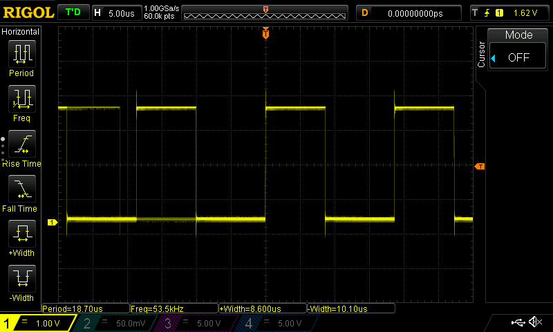
Which can be verified by connecting the oscilloscope to the pulse pin on the ESP8266 with nothing else connected:
Note that the oscilloscope does the measurement hard-work for you when you press the +Width and -Width buttons on the left side of the screen, displaying times helpfully along the bottom of the screen.
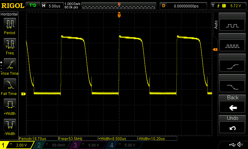
Then connecting the ESP8266 3.3V, GND and pulse pin to the V1.1 prototyping board, we get the following trace:
And now for the all-important brightness comparison. It's hard to convey the difference using a mobile phone camera and words but I'll give it a go:
Yapolamp Beta (Left) with all LEDs and Yapolamp V1.1 protoboard (right) with 2S 1P configuration.
You can see what I perceive in this photo, that the Beta is slightly brighter than the V1.1 protoboard. However, I thought it would be fairer to compare 2 LEDs to 2 LEDs, so masked three of the Beta with electrical PVC tape:
Although the focus is frustrating, their brightness is closer than I initially thought. I went back to the efficiency calcs to see what driving at 20mA peak sawtooth current would do to the efficiency - it would be about 0.91 at 317 Lux/mA relative to the peak efficiency of 348 Lux/mA. Worth considering. Lets see if we can tel the difference in a comparison. According to Spice, we'd need a 12-13us pulse and we would catch the downward voltage slope of the inductor about 14us later. Now to generate that profile on the ESP8266, we need:
voidloop() {
digitalWrite(D4, HIGH); // pulse ON
delayMicroseconds(11); // generate a 12.5us delay
digitalWrite(D4, LOW); // pulse OFF
delayMicroseconds(7); // generate a 14us delay
}
This timing needed tweaking so that the next pulse catches the downslope from the inductor in reality. This is the beauty of having an oscilloscope to verify what the simulation says. We now need a 13us wait before sending the next pulse. To compare the 14mA and 20mA versions, we will cycle between them, one cycle per second, so each mode will be on for 500ms. Because of the delay introduced by checking the time for pulse length cycling, this is what the code results in for now. You wouldn't go to production with it, but it suits our prototyping needs:
byte pulseOn = 6;
byte pulseOff = 0;
unsigned long present = 0;
voidsetup() {
pinMode(D4, OUTPUT); // initialize digital pin as an output.
}
voidloop() {
present = millis();
digitalWrite(D4, HIGH); // pulse ONif (present % 500 == 0) { // action this subroutine every half secondif (present % 1000 == 0) {
pulseOn = 6; // ON delay if at a full second
pulseOff = 0; // OFF delay if at a full second
}
else {
pulseOn = 10; // ON delay if at a half second
pulseOff = 3; // OFF delay if at a half second
}
}
delayMicroseconds(pulseOn); // delay for the inductor to charge
digitalWrite(D4, LOW); // pulse OFF
delayMicroseconds(pulseOff);// delay for the inductor to discharge
}
We got our nice pulse traces, as desired:
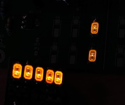
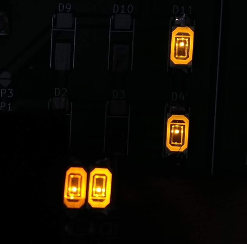
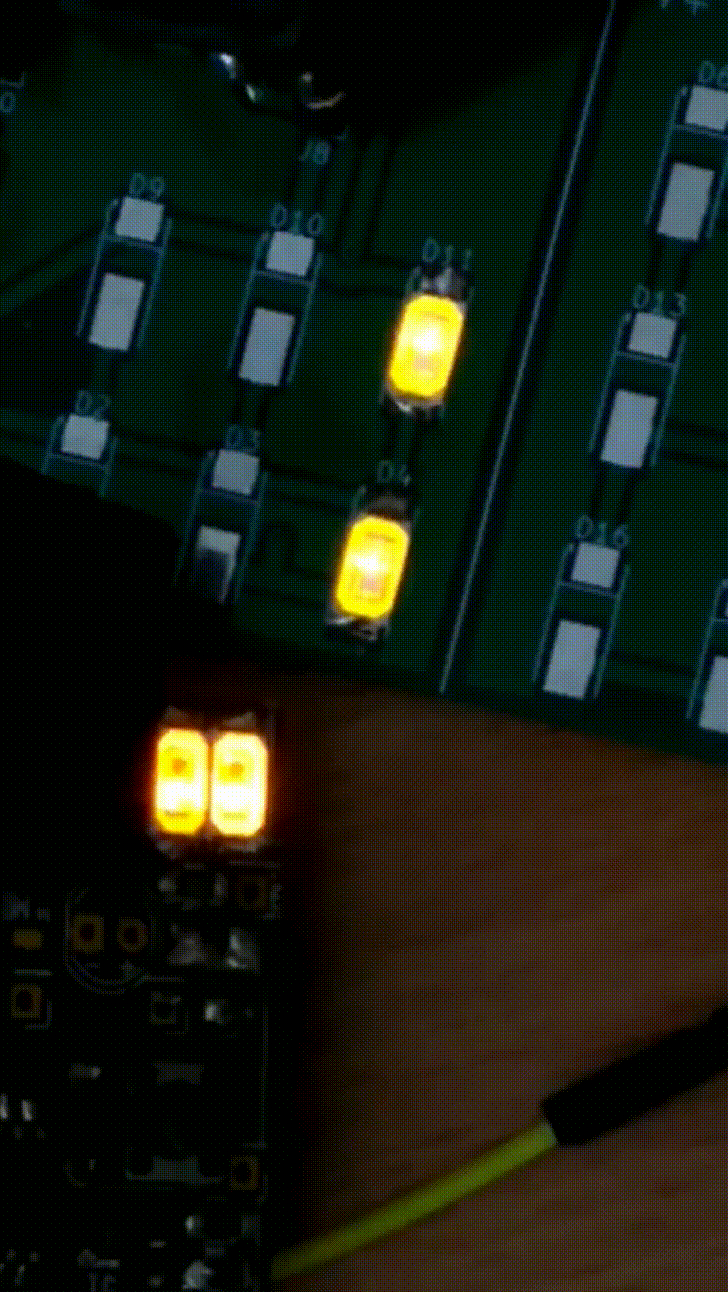
And there is a minor increase in brightness (which is expected, as perception of brightness is not proportional to illuminance). The Beta is the two close-together LEDs in the bottom left and the top right pair are V1.1 protoboard cycling between 14mA and 20mA peak sawtooth current:
That said, I still don't think they're quite as bright as the Beta. I will try and analyse the current in the Beta design at some point in future, perhaps when I get my Joulescope next month. However, the Beta LEDs seem a darker colour and are definitely warm to the touch (the V1.1 LEDs seem to be at ambient air temp), so I would say that they are running at MUCH higher currents than the 14-20mA we're pulsing at peak through the V1.1 LEDs. So if we can't get and equivalent brightness from the V1.1 LEDs, will it work as a torch? The only other basic way I can think of is to solder the other 4 LEDs onto the protoboard and run the full 6 in a dark room and make a call. There's every chance that they will still be bright enough for our original use case, which we set a long time ago but haven't really needed to change:
1) A torch for the user to find their way around a dark room or for limited reading under a duvet.
Next time, we'll look at the 6 LED solution in 2S 3P arrangement.
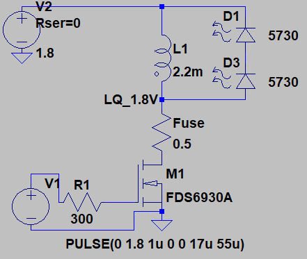
Having played around looking for the optimal sawtooth current pulse, my last log concluded we were aiming for 12-14mA peak, at the start of the pulse. I took this to LT Spice to see what pulse times would work with what inductor values and voltages to achieve this. Remember that in the next version (V1.1) of #Yapolamp we're planning to use supercapacitors to run the thing, so we are likely to see a large range of supply voltages. For now, I will say our planning range is 4.7V, the top charge I expect to get the capacitors to, to 1.8V, where the ATtiny will stop being reliable.
The first Beta Yapolamp uses 5 of the Chanzon 5730 LEDs in parallel (with that crazy "it shouldn't work" inductorless driver circuit). For some reason I think we'll be looking at 6 LEDs in total this time (more layout options) and I think we should try driving a 2 Series 3 Parallel arrangement. I'm not aware that there are any huge disadvantages of driving 2S 3P over 6P - your inductor needs to generate a larger pulse voltage to overcome 2x the forward voltage of your LED but the current is kept lower. Indeed, driving LEDs without individual current limiting on each circuit line is frowned upon, so moving to more LEDs in series is returning towards "good" practice, at least nominally.
So to start off this round of simulation, I will only use a pair of LEDs in 2S 1P configuration, with a 2.2mH inductor.
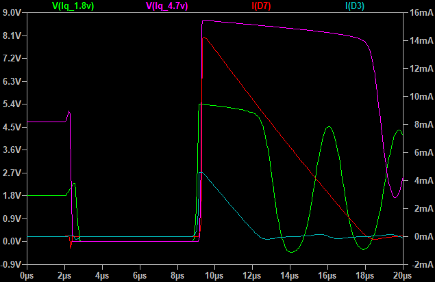
I want to see what the voltage range does to the peak sawtooth current. I found with a 4.7V supply (Vpulse is the same as the supply) and 6us pulse pulling the inductor to ground (pink trace), we get our 14mA (red trace) peak current. However, that same pulse length (green trace) at 1.8V supply only manages a measly 4mA (turquoise trace) peak current:
If I want to match them up, I need to give the 1.8V system a 17us pulse. Here's what that looks like against the 4.7V 6us pulse (delayed the 4.7V system pulse so the sawtooth discharge currents align):
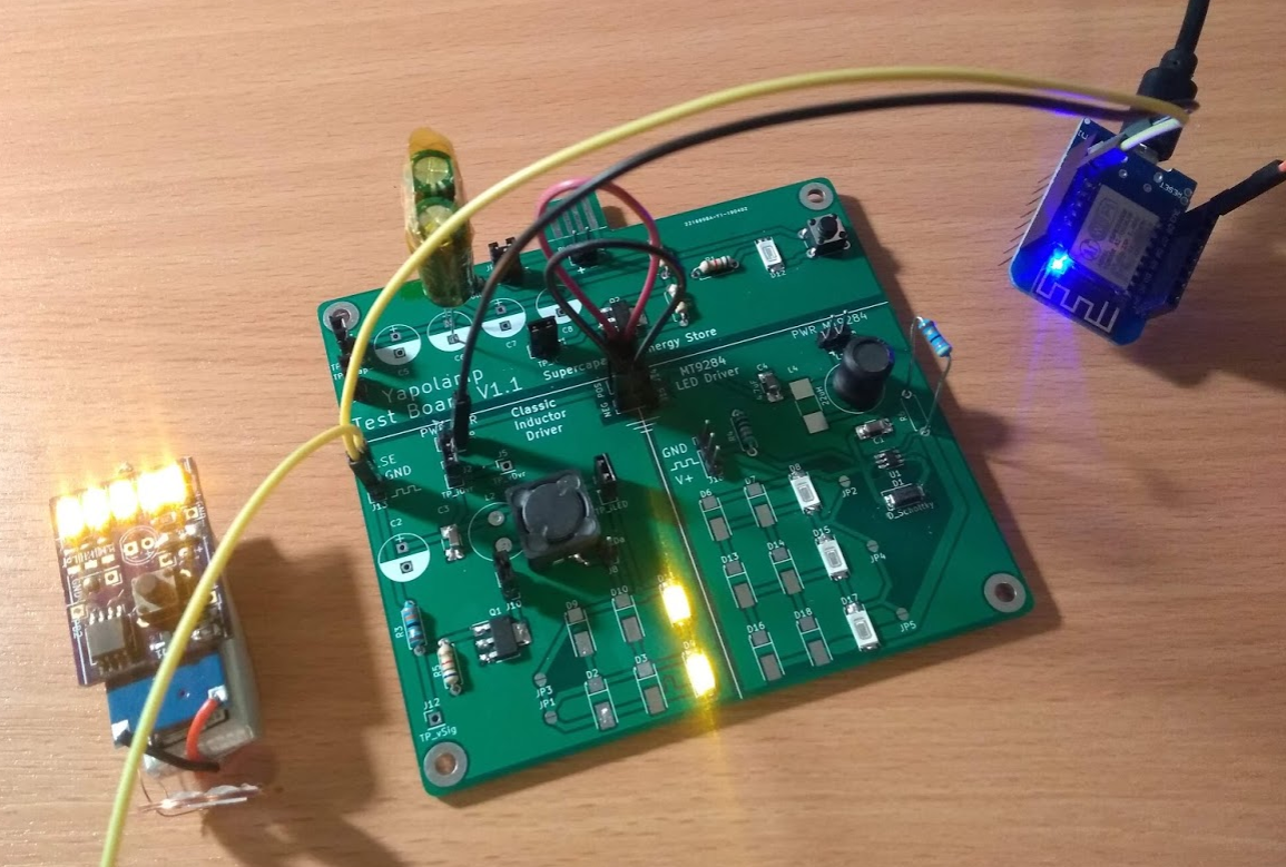
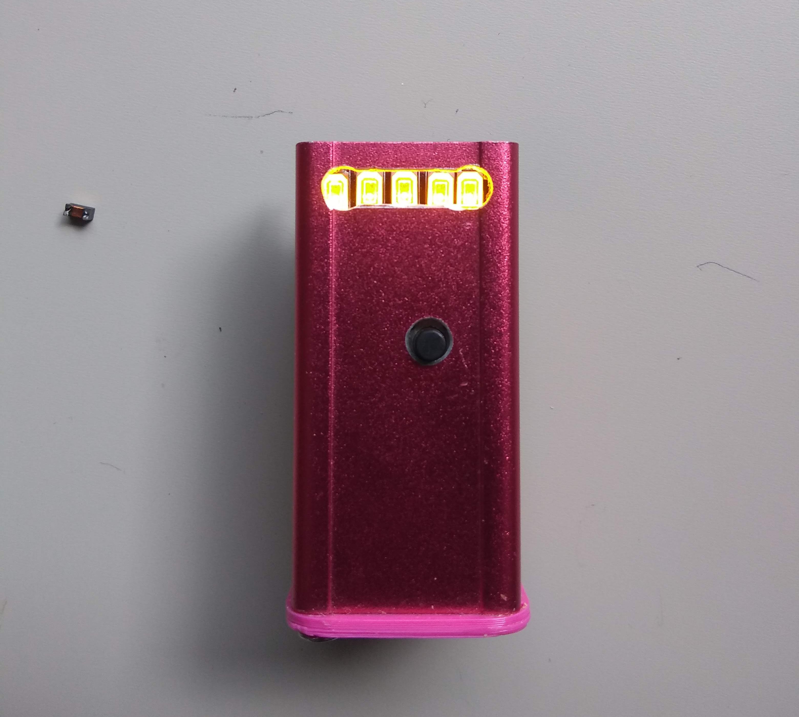
Let's leave Spice there for now and just update on some of the playing I have done with the prototyping/test board. I have connected both the classic driver and the MT9284 sides as well as populating the supercapacitor chargin circuit. Here you can see the supercapacitors powering two LEDs through the classic driver with a 2.2mH inductor and a 3V pulse from an ESP8266.
I'll do a more detailed log on the MT9284 another day but for now it gives me too many concerns to use with supercapacitors, due to it's ultrabright startup and then noticeable drop in brightness, audible whining and then very quick burn through the supercapacitor charge. I don't think I want to pair that IC with supercapacitors for now, although for more stable power sources it's definitely something I'd consider. It also cuts out at 2.2V and although that's not far from the cutoff voltage of 1.8V for the ATtiny that is likely to be driving pulses in the V1.1 Yapolamp, the classic driver has been putting light out down to below 0.5V on the capacitors! I admit I haven't completely ruled out the pulse input being significant in this observed performance (although there's a low value resistor in there). If it was a driver circuit that could light LEDs down to 1V, I don't know how I'm going to take advantage of that yet. It would be amazing to go into a distinct version of the always-on mode which told you that you need to charge the Yapolamp before you can use it in full mode. Could the microcontroller do high level management of it's a joule thief or charge pump for self operation down to those low voltages, say by kicking it in at 1.8V?
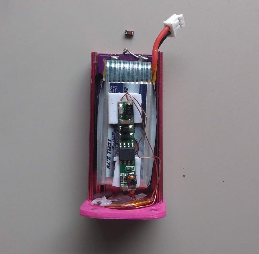
My first design flaw was to make this board for a single supercapacitor in series and several in parallel. That was silly because most of the supercapacitors I'll want to use will only be ~2.7V rated, so will need to be paired in series. For now I have twisted the legs of two capacitors together in the middle and taped them out of the way with kapton tape, before soldering the pair into the holes for one capacitor. They are 3F Cooper Bussman jobs. I can fetch part numbers if anyone is keen but I plan on using larger capacities in the full V1.1 design, as the pricing doesn't seem linear, run time is always in short supply with full brightness mode. With a totally unoptimised pulse regime of around 22us pulse on and 18 us pulse off, I'm getting about 5 - 10 minutes from a single pair of LEDs and a 3F capacitor battery. I think a couple of pairs of 10F 2.7V capacitors for an overall bank size of 20F would fit within the existing form-factor and provide good run time over 6 LEDs.
I have managed to charge the capacitors successfully several times from a USB battery pack, so the tab is good. It would need a shim or to be made on 2.0mm FR4 for the final version, in order to push the contacts together when inserted into the USB battery - 1.6mm is cheap but too thin for USB connectors.
One concern I have from the current charging circuit is that the supercapacitors appear to discharge even when well disconnected to other parts of the circuit, such as the LED drivers. I had the supercapacitors in a breadboard before and I know they don't self-discharge in a noticeable way like they are now. Any thoughts on what is causing this? Do Schottkys leak? Bear in mind I've observed this with J11 disconnected too...
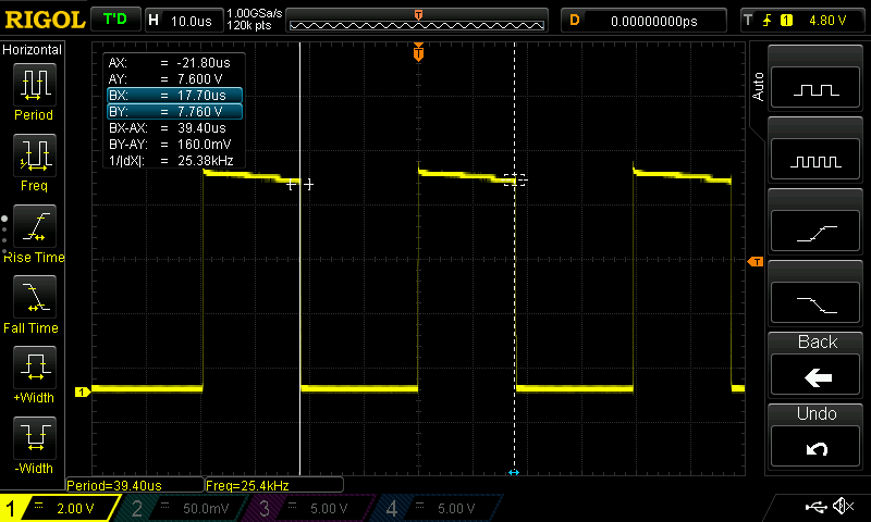
I'll finish up this log with some measurements from the oscilloscope at the connection between the inductor, MOSFET and LED. They look reassuringly similar to the Spice plots. Hooray!
First up is "the curve I was aiming for". This is some time into the discharge, say 30 seconds to a minute and capacitor voltage will still have been more than 3V (sorry for the vagueness - was really poor at noting observations tonight)
Next is what it looked like when I disconnected the USB battery that had been charging the capacitors. The inductor's discharge into the LEDs is cut short by the next pulse, which isn't what we want as this will be wasting energy in the inductor's magnetic fields that could have been converted to photons yet was cruelly "earth spiked" (note the different time base - all durations are the same length as before):
Finally here's what things look like when the capacitors have discharged down to about 1.8V but the pulse regime has remained the same:
Pretty sad but let's hope we can address all this with smarter pulse lengths in a future log. It's also lovely to see the oscilloscope trace resemble something you made in LT Spice. I'm starting to trust the tools more now!
So after the debacle in the last log where I discovered I have completely connected up the MOSFET wrong in the very first #Yapolamp and by some freak phenomenon it not only works but it works without an inductor, we return to normal viewing.
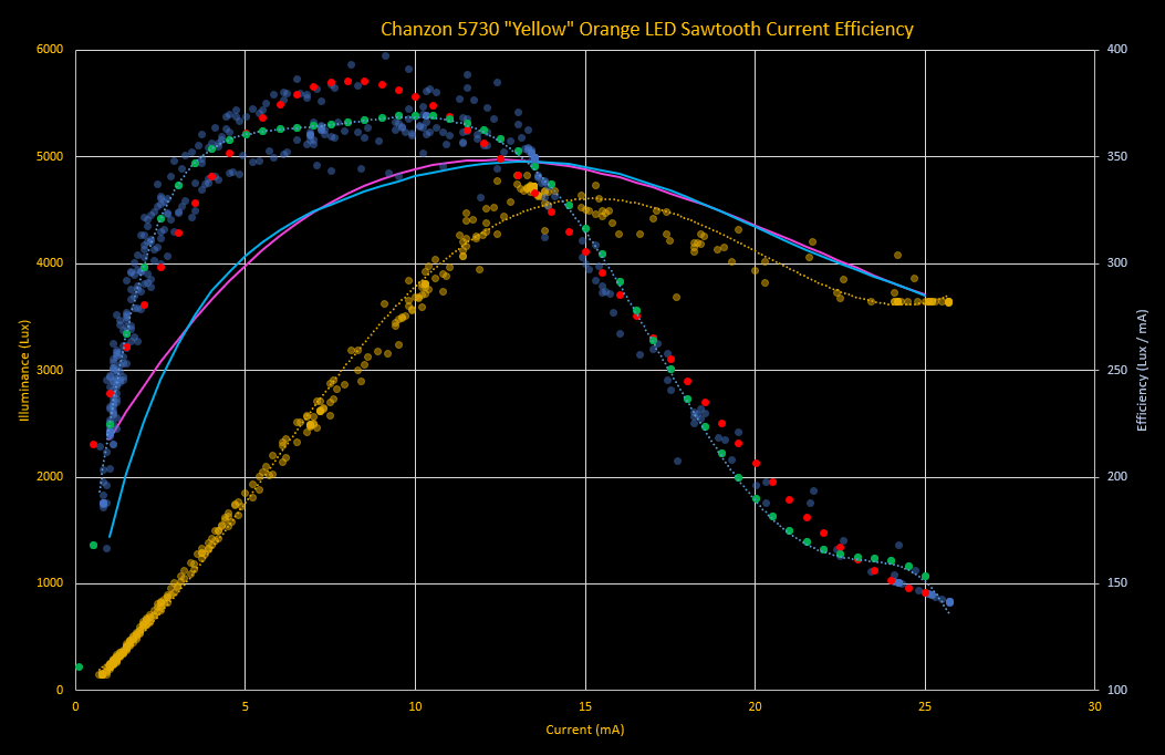
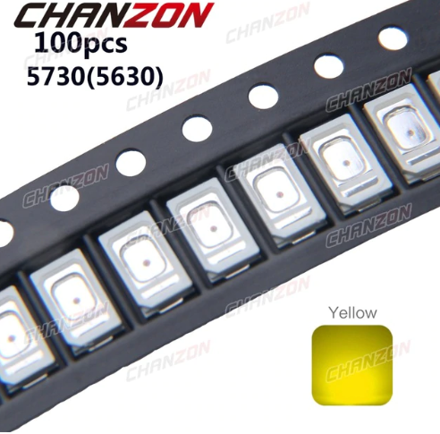
A couple of logs ago, I showed my first current/illumance graph for the Chanzon yellow LEDs (which produce orange light, if you ask me). I blatantly copied this from #TritiLED 's search for the most efficient way to drive an LED for your coulomb. We opted for the far less rigorous unit of Arbs in #Yapolamp . Today, I went to the next step that #TritiLED did which is, once you know how many Lux you get for each mA, to try and work out the optimum saw tooth peak (initial) current to drive the LED with. This is different to the peak efficiency current because as current decays to zero (imagine the inductor disharging into the LEDs in our driver circuit), it passes through the efficiencies of all the lower currents.
When @Ted Yapo did this properly for #TritiLED , he used octave plots and normalised everything because he knows how to do that and it's good practice - normalised values let you do comparisons etc. As you may have picked up on by now, #Yapolamp differs from it's namesake by being somewhat less rigorous and skilled. I just used Excel. I assumed the same as Ted that my current would step up instantly to peak value and then decay linearly to zero. I used 10 time steps as a proxy for proper integration, worked out the time-step current based on an initial peak value and calculated the Lux/mA at each step. I then took the mean Lux/mA across all time steps for a given peak current and plotted them over my graph from last time.
Note that I had trouble finding a good polynomial trend line to my data - those measurements were all over the place, so no wonder Excel had trouble. The ^3 trend line (red dots) looks nice in most places but overshoots a bit around 7mA and at lower values. The ^6 curve (green dots) is better in most places except it goes a bit wrong above 13mA. I decided to plot the optimum sawtooth current curves for both to see how they differ.
The main takeaway is not the comparison between the polynomial trend lines but how the optimum peak currents (pink = ^3 trend line and blue = ^6 trend line) are higher than the most efficient static currents. This was expected, thanks to Ted's work, but it's nice to see the curves superimposed for contrast.
My conclusion is that for our 60mA-rated LEDs we're looking at a peak sawtooth current of around 12-14mA. I seem to recall Ted forming a rule of thumb from his observations that about 20-25% of rated current was where we'd expect to find peak efficiency. I just can't remember whether that was static current or sawtooth peak current!
Now I have a design current to take into SPICE and this time, who knows, maybe we'll design something with the parts connected the right way around.
I'm mystified. I now have the prototyping board to try out supercapacitor power and compare the MT9284 driver scheme with the original inductor boost circuit. I decided to tear down the original Yapolamp Beta (I know changing from Beta to V1.X isn't helpful). As you may remember, the whole impetus for a V1.1 was that the original had stopped working. Here's what I found:
That cheeky little inductor I was so keen on for its low profile has completely come away. I think I'll share the blame for poor soldering with the fact that the bonding pads on the inductor were probably not designed to be dropped as much as the Yapolamp has been. It was nestled in behind some PVC insulation tape I had lined the enclosure with, thankfully not causing any short circuits with my lithium battery.
Now for the weird stuff.
So then I happened to touch the two pads where the inductor should have been with a finger and the Yapolamp glowed into life!
WITH NO INDUCTOR!
It didn't just glow, it had full function. Button presses cycled between the always-on and full-brightness modes. I left the full-brightness mode on and sure enough, after several minutes it started to blink to signal to the user that it would be turning itself back to always-on mode if you didn't press the button again...
WHY IS THIS WORKING?
I can understand the ATtiny85 running properly but how can the reverse-connected LEDs be driven if they're not connected at one end and the other is only connected to Vbat? Inductor PCB pad acting as a capacitor? Ideas gratefully received in the comments...
<EDIT> Hopefully you can see the pictures now @Ted Yapo - I think I used a link from Google photos. They're now uploads.
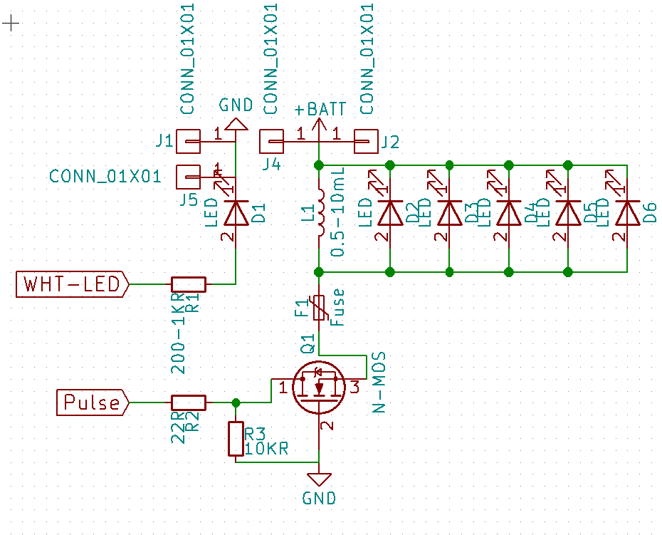
Now I'm even more confused. Here's the schematic from last December:
Ignoring that white LED (which I never felt the need to fit) and the fact that I shorted across the fuse terminals, can you spot the error? Yep, that N channel MOSFET appears to have a pulse driving the Drain, with the Gate pulled to Vdrain by a 10k resistor and the Source at the same voltage as the LED anode... how is ANYTHING working here!?!
I looked into a charge pump as an LED driver. I concluded we'd waste too much energy unless we bought several MOSFETS, especially as the losses associated with diode voltage drops would be significant at the low voltage of our storage medium.
I looked at a "proper" LED driver chip, the MT9284, which seems to be a design offered under different part numbers by at least three different vendors. These chips do the boost for you to up to 7 LEDs in series, if you give them an inductor, Schottky diode and some caps. They claim high efficiency (c. 90%) but across the voltage range of 2.2 - 5V fixed feedback resistors struggle to provide a constant current. Also, unsurprisingly, the greater the number of LEDs in series, the lower the current they appear to provide. I'll explain a bit more in another log.
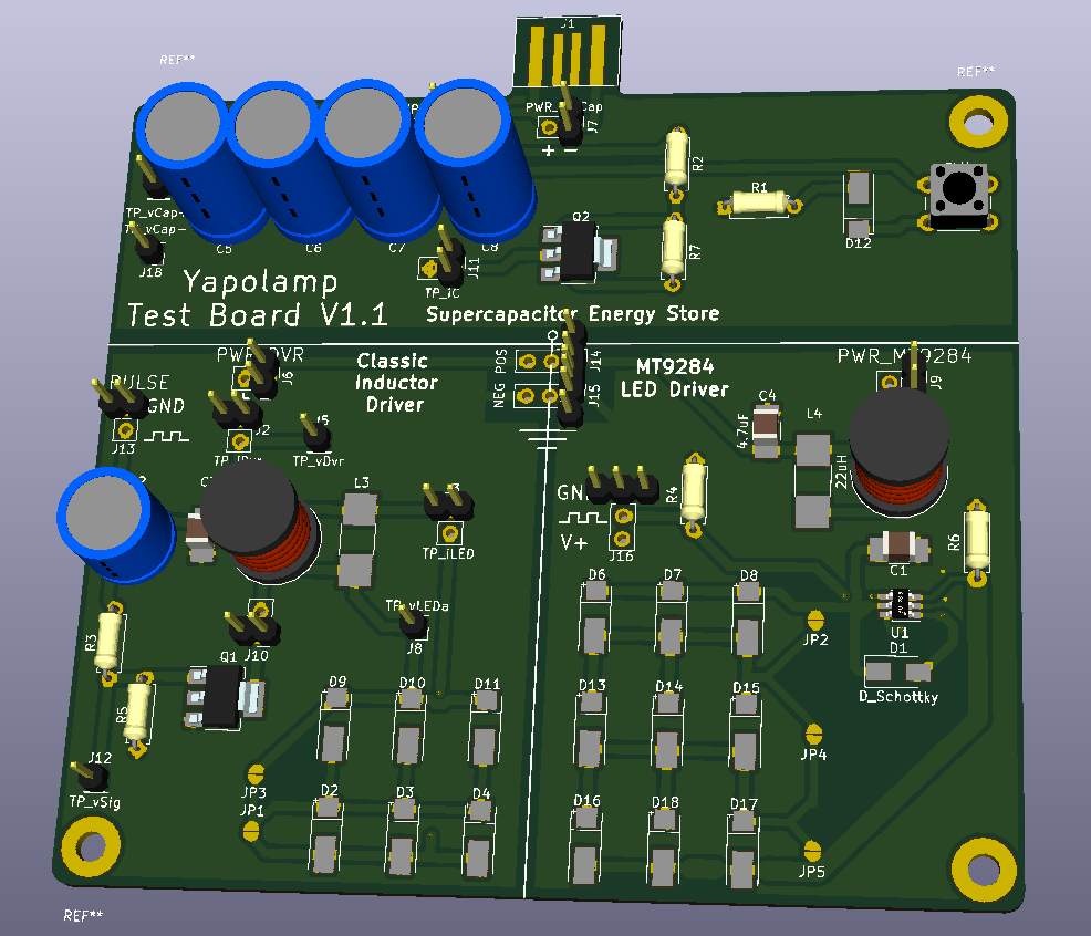
I have ordered a single PCB to test the "original" inductor flyback driver that Tritiled and Yapolamp V1/beta use and compare against the purpose-built MT9284 LED driver.
Getting closer to an LED "Arb" Rating
For this log, the main information is the result of an efficiency test for the "yellow" (orange) LEDs I'm using in Yapolamp. In previous logs I have described why these are a nice colour for a night light (warm, don't spoil night vision, comforting if you grew up with a high pressure sodium street lamp shining through your bedroom window, don't damage your eyes much...). We're going to stick with them for the foreseeable.
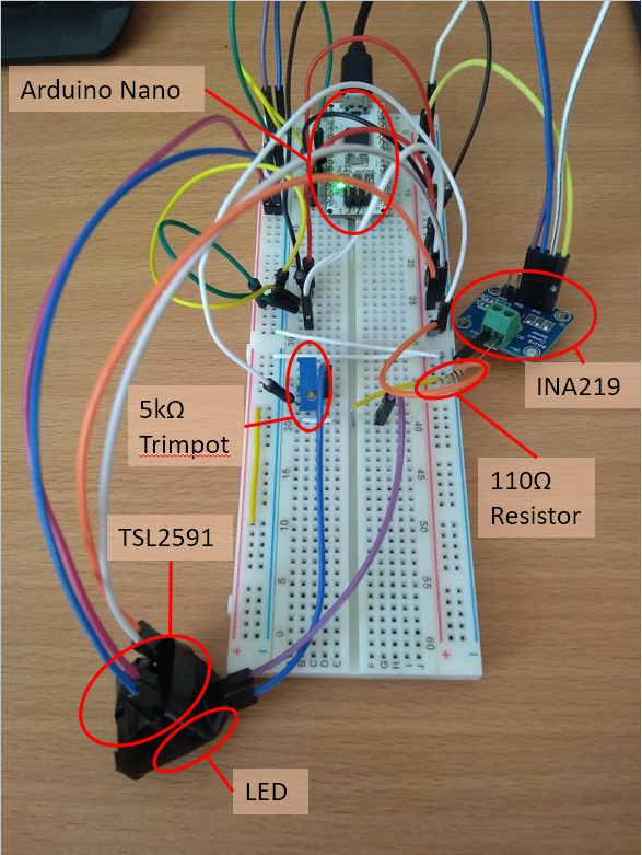
@Ted Yapo properly characterised LEDs for #TritiLED in Arbs but I have used more of a lash-up rig to find the peak efficiency of these Chanzon yellow LEDs. I taped the LED to the TSL2591 light sensor with a 5mm piece of acrylic/HIPS between them and covered the pair in black electrical tape to reduce interference from outside the LED. An INA219 was pressed into "high precision, reduced range (400mA max)" mode to measure the current from 0.8mA to 26mA, set by a trimpot and fixed resistor in series.
Which yielded the following results:
So rather strangely the light output (yellow data points) started to drop off after 13mA and the peak efficiency (blue data points) appears to be in an elongated region between 6 - 12mA. This is in line with Ted's observations that peak efficiency is balanced with "cost of die area" in LED economics to produce the higher recommended current ratings; 60mA in this case. The broad magnitude range of 6-12mA for the high efficiency zone bodes well for achieving the "peak sawtooth" efficiency that Ted calculated for Tritiled.
Sorry, I didn't have time to convert results into the internationally recognised unit of Arbs that such a lash-up measurement rig deserves.
Please jump into the discussions for any handy observations or tips about how you go about calculating or designing that "peak sawtooth".
Super Power
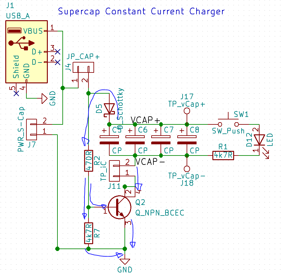
You may have guessed but the plan for this version of Yapolamp is to use supercaps as the energy store. Initial tests and spec sheet leakage figures seem like they'd fit the use cases of short run times at high brightness and longer term low-glow levels so the torch can be found in the dark. By adding a transistor based constant-current charging circuit and an anti-backfeed Schottky, we could let the (young) user recharge in under 30 seconds using a USB battery pack and run for many minutes at full brightness, even after a few days in "always on" standby mode.
Here's an unfettled image of the test board I ordered, from the Kicad 3D viewer.
PS, the purpose built LED driver ICs are ~$0.05 each in qty 1-10 so they are potentially a really good option for many other LED circuits.
I'm going to put my naive inductor investigation on here so that hopefully the comments will come alive with illuminating advice.
Firstly, I found this website which tells you how to use the "ring down" method to evaluate the losses of inductors. Great. It says the rise/fall time of a 555 timer is too slow to drive the "hitting" of the "bell" that is the inductor. Quick search say's that's 100 ns. How fast is my ATMEGA328P based Arduino or my ESP32? Oscilloscope to the rescue:
Here's the Arduino running at 5V - rise time is 4.5 - 4.8 ns
And here's the ESP32 running at 3.3V - rise time is 2.8 - 4 ns
I think we'll stick with the Arduino for now, but we are roughly looking at the same gradient, just different voltage levels.
So my first setup used the "weak capacitive coupling" method for driving the inductor (see website link above) and looked like this (driven by pulses from the yellow wire on the left):
Which resulted in this measurement on the 'scope:
For the ring down method, we're looking for how many oscillations happen before the amplitude halves. In this case, with a 7.2mH TDK inductor I got. It's not looking good, so like an exasperated parent thrusting their child towards a godparent to "talk some sense into them" I asked the eponymous Ted Yapo what might be going on and he said my scope could be stealing some of the energy it's supposed to be measuring.
So I added a 9.1 MOhm resistor in series with my 10x probe in an attempt to slightly improve things. Here's the lash-up rig with the TDK inductor attached at the bottom. You can't see the parallel capacitor but it is there!
Here are the respective results shown on the 'scope with nothing changed:
TDK:
Bourns ( did zoom around but couldn't find any oscillations that looked like it was ringing):
Coilcraft 3.3mH:
Coilcraft 6.8mH:
Coilcraft 10mH:
Suffice to say, I probably shouldn't have used that Bourns inductor in the V1 Yapolamp. It will be interesting to see where the failure of that version may be found to lie. I also have a different energy plan in mind for the V2, so there would potentially be more budget (as if I even have a budget!) available in the BoM for a nicer inductor.
Or maybe, where we're going, we don't need inductors...
So, we're a year on from Christmas 2017. What's going on with the Yapolamp?
I wanted to review the year we've had with the torch as we've now had the best part of two winters with it in use by my son. He has been thrilled with it and loved having it set "on" (bright) at bedtime, to then go into "always on" (dull) mode after about 12 minutes. The battery would last just under a week in this use profile and then get charged up overnight. I never got around to encasing the charging Tx coil in anything, so it has been sat as a bare circuit and coil on my nightstand and plugged into a USB phone charger when needed. The aluminium case always got tepid/luke warm during charging but I was never concerned about charging the torch.
My son also really liked exploring dark corners of the house with his Yapolamp, especially navigating his way to our bedroom on dark winter mornings. We love the Yapolamp as much as our son as it's a good way to have more light in the children's room for e.g. administering Calpol at 3 a.m., without waking everyone up too much. Thanks to the "always on" mode, it's always easy to find in a darkened bedroom.
Sadly, in the last month the torch has stopped working properly, with all LEDs going dark. Charging puts it into "always on" mode briefly and sometimes pressing the button will turn it to "on" mode but more often than not, it turns completely off. I had always wanted to look at the efficiency of the LED driver circuitry (particularly the tiny inductor I used) and had wondered about the effectiveness of the wireless charging and battery life over time.
Since making V1 of Yapolamp, I have acquired an oscilloscope so can now actually check the reality against the theory of the LT spice simulations I did during the design (and then bodged around with NOPs to get a reasonable average current draw).
So my intent for Yapolamp is (in no particular order, apart from 4):
Teardown V1 to see if I can spot a failure mode
Try and view the performance of the LED driver circuitry
See if I can discern whether a smaller-size inductor was a bad choice for the LED driver
Design and build a V2 Yapolamp, with today's older and less-inclined-to-lick-electronics son in mind...
Quick picture log to show the progress of integrating the wireless charging circuit in the torch (charging dock will come later) and cramming the internals into the case:
Charging LED comes on when placed on charging coil - draws a couple hundred more mA, probably due to the eddy currents in the aluminium enclosure, when it's fully wrapped round.
All sealed up:
The beta is done - it'll get unwrapped on the 25th and we'll see what the user thinks (crikey - I'm not sure I'm ready for that level of honesty). There are "things to do" in the next version, e.g.:
MORE SAFETY - the beta doesn't implement the safety features above those in the TP4056 module protection circuit and the LiPo battery's internal protection. I'll add @Ted Yapo 's recently suggested capacitor and PTC fuse circuit.
Use the tiny SMD inductor mentioned in the previous log, get all components onto one side of the PCB and review the overlap with the TP4056 module to try and become more compact.
Better mechanical assembly - the protruding momentary touch button doesn't make for smooth assembly with the PCB mounting grooves in the current enclosure. The LEDs are also too far from the window slot.
Better mechanical user interface - perhaps a lanyard or strap loop or two. Perhaps a ring to protect the button against accidental pushes (but the auto-off/always on feature helps protect against this becoming an issue).
Proper window/lens for the LEDs. And a way to see the charging LEDs lights.
Low battery mode; a distinct visual cue to tell you to charge it.
Reduce the inefficiency of the eddy currents in the aluminium enclosure - perhaps by increasing the depth of that bottom printed plastic section, perhaps by ditching this enclosure style.
Make it easier to disconnect the LED driver circuitry from the ATtiny85 for loading new code (it roundly ignored the Arduino Nano as ISP requests to programme it).
Just to reassure those worried about only major circuit protection being in place at this stage, it will only be allowed to be used in the bedroom for now and charging will be done by the grownups and the battery attended by an adult during charging.
That's it for #Yapolamp this year - Happy Christmas!
Here's what it looks like (ignore the jumper - that's where a fuse might go. It currently won't allow the ATtiny85 to be reprogrammed in circuit with the battery power connected and the jumper was faster than disconnecting the JST on the rear):
Endurance
I did some testing for battery duration. It's clearly less efficient in "On" mode than I expected but that's fine - I still got around 2hrs runtime constantly. The lower than expected duration could also be due to the charging of the battery, as the current firmware allows the "Always On" mode to run while charging, so there will be a base current which may affect the cut-off point of the TP4056 charge profile.
In "Always On" mode, I set it going and left it in my car. For 2 weeks. Here it is after 14 days in temperatures between -5C and 12C:
I don't know how long it would have gone - it still had power for "On" mode:
Shrinking the Inductor
I managed to find a 2.2mH inductor that is drastically smaller than the other ones, with a reasonable resistance of 1.2 Ohms, the Bourns SRF3216 Series Type 3216 Wire-wound SMD Inductor with a Ferrite Core. They are also 20% of the cost of the larger one's I've been using. You can see it bodged onto the larger footprint here (by the JST plug):
I think this means the next revision of the board will have all components on one surface, giving more flexibility over the mounting with battery and TP4056 module.
Wireless Charging
Finally for this log, I want to admit I have finally realised that a "safe" and simple charging setup should have considered wireless charging a long time ago! I recently saw a product that implemented it well in a prototype and I looked into it more, I want to fit the coil in quite a small enclosure, so I went for this wireless charging module which is rated for 300mA (I have a module charging a 250 mAh battery, so this suits a 1C charge rate - BTW, you need to change the charge current resistor on the TP4056 module if you want to charge small LiPos at a safe 1C rate).
It doesn't charge through aluminium (unsurprisingly but I had to just check). Ignore the power supply in the background - it just draws full current and heats the charging chips, so I turned it off:
Finally, here's the proof of concept GIF showing the ability to transfer the charging current (into the motor). Note the 100 mA standing current that the charging transmitter circuit uses even when the receiver coil isn't in working proximity. The other thing to mention is that the direction of the coils appears to be significant - the ~250mA peak in the GIF rises to over 400 mA (ie the max I set the power supply to, for safety) if you flip one coil over.
Next Up
Integrate the coil, print a replacement for the aluminium end panel, machine the button hole and LED window slot in the enclosure and perhaps mould an epoxy window in the slot. Oh, and make a charging dock...
Sorry, no pictures this time but perhaps the news that the Yapolamp code is "done" enough to warrant its own Github repository is exciting enough to make up for that!
So, after trying a variety of approaches, I now have the main software features implemented:
Short, timed pulses to drive the MOSFET, "charge" the inductor and then pulse the LED bank on. This was achieved by using port manipulation and assembly language NOPs to ensure the additional clock cycles of e.g.
delayMicroseconds()
weren't adding significantly to the timings, especially the duration that the MOSFET was allowing current to pass. I used both Nick Gammon's approaches to work out if the higher level language was adding unnecessary delay. The first, using the Profile Timer Code makes it possible to monitor the device you are running code on and allows you to capture the duration of execution of code sections you specify. Unfortunately, using an ATtiny85 made it difficult to interface with a serial connection, so I ran the code on an Arduino Nano clone. The resolution was 4uS, which I would have preferred to improve upon, as I knew my ON pulse should be around or less than 4uS. Next, I used Nick's Frequency Counter sketch for Atmega328. It runs on a second device to that of the device under test, so I made the device under test the ATtiny85 and the Arduino Nano clone ran the frequency counter sketch. You connect the D5 pin to the pulse source (PB1 in Yapolamp) and it gives you a count of pulses over 1 second, which are then easy to convert to a period duration with a calculator. This is what really showed me that the port manipulation and NOPs were enabling much faster and finer resolution pulses and pauses:
Low power ALWAYS ON mode. I used the sleep and watchdog timer features of the ATtiny85. By setting the watchdog timer to fire every 32mS, you can achieve around 30Hz blink rates and therefore it appears as a solid, low brightness light, thanks to the Persistence of Vision effect.
Toggling through modes. This was a real challenge for me. For a couple of evenings I struggled to get a reliable button press registration, despite using Nick Gammon's software Debounce without Delay code that I have used sucessfully before. After a long time I realised that the Nano's D5 pin was still connected to the pulse pin - PB1 on the ATtiny85. Along with a capacitor across VCC and GND, disconnecting this made everything work. I think the capacitor is fully warranted because the voltage spike of the inductor must be significant (at around 50kHz!) and I will need to include a capacitor in the next revision of the torch PCB. A leaded capacitor across the battery connection will do for now. Once I had a button input sorted, I needed to set up Yapolamp so that it would self time the ON period, before switching to an obvios "wind-down" period. As the user notices this wind-down mode, they can then press the button to start another full period of ON. If they don't do anything, the Yapolamps times a further short period before moving into ALWAYS ON mode to save power until needed again. I tried using this with an
if (millis() - oldTime > waitDuration)
approach but from an interesting post on StackExchange and subsequent analysis, millis() would appear to take just under 4uS and I didn't fancy relying upon the "mode code" to produce part of the pulse delays. So, before resorting to setting a timer up, I looked at using the watchdog timer but without the often associated sleep function. It took me a while to realise that you need to call it every time the previous one ends (not every "loop" and not "once") but now I can reuse the watchdog code I'm already using with sleep function for the ALWAYS ON mode. It seems to work quite nicely, although there is the odd instance where it refuses to go back into ALWAYS ON, after a period of ON and wind-down. A little more reliability work required here.
So, all in all, I'm very happy to get to this stage. Please go and have a look around the sketch on Github. I'll try to upload some schematics another day and then other people can have a go!
 Simon Merrett
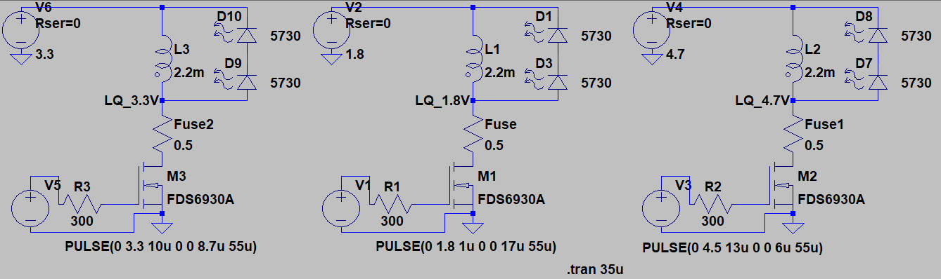 As before, when I compared the 1.8V and 4.7V supplies, I have adjusted the pulse start times and durations so that all the voltages have their discharge current curve superimposed:
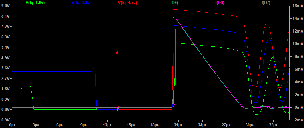
 Although the focus is frustrating, their brightness is closer than I initially thought. I went back to the efficiency calcs to see what driving at 20mA peak sawtooth current would do to the efficiency - it would be about 0.91 at 317 Lux/mA relative to the peak efficiency of 348 Lux/mA. Worth considering. Lets see if we can tel the difference in a comparison. According to Spice, we'd need a 12-13us pulse and we would catch the downward voltage slope of the inductor about 14us later. Now to generate that profile on the ESP8266, we need:
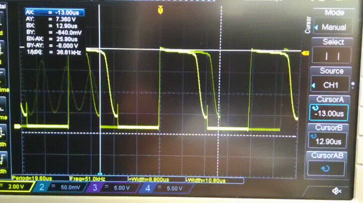
 I'll finish up this log with some measurements from the oscilloscope at the connection between the inductor, MOSFET and LED. They look reassuringly similar to the Spice plots. Hooray!
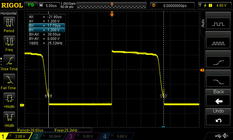
 Finally here's what things look like when the capacitors have discharged down to about 1.8V but the pulse regime has remained the same:
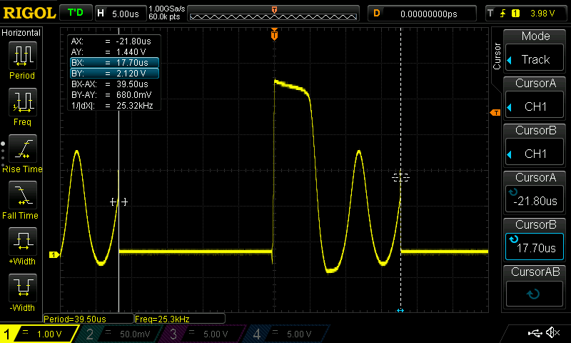


 I don't know how long it would have gone - it still had power for "On" mode: