 Bud Bennett
I'm just figuring out how Hackaday projects should be organized. I will have to go back to the details section and clean it up to reflect the current project status. But this log will cover changes made to the first version of the UPS that uses the TPS61236p booster chip.
The INACT pin was supposed to be high if there was a light load on the booster, and go low when the booster a load current greater than 50mA. Unfortunately it didn't work that way. Here's my theory: the INACT pin function requires the booster to be switching in the low current burst mode. When the wall wart is providing power it holds the output voltage slightly above the target voltage of the booster which prevents the booster from switching. Therefore the INACT pin doesn't work and is set low by the TPS61236p, which is the wrong state and causes the battery charger to be shutdown and the PWRGOOD status bit is incorrect when sent via the I2C interface.
The fix is to provide a PWRGOOD signal by sensing the switching action of the booster. Instead of revising the UPS-NOSWITCH design I decided to put the changes into the alternative design using a 14500 battery. This board is named UPS-14500-IS because it is designed for the smaller Li-Ion 14500 form factor and includes an input switch to disconnect the load from the wall wart. The layout on this smaller PCB is more cramped and therefore more compromises were made so I figured if this smaller board worked then the larger 18650 form factor would be a walk in the park. The 14500 battery has a capacity of around 700mAh, so the UPS is not going to provide hours of operation. The primary task of the UPS is to hold up the power supply for a minute, or maybe up to 10minutes, and give the Raspberry Pi time to shutdown its systems and power down so that no damage is done when the power is removed.
Here's the schematic of the UPS-14500-IS:
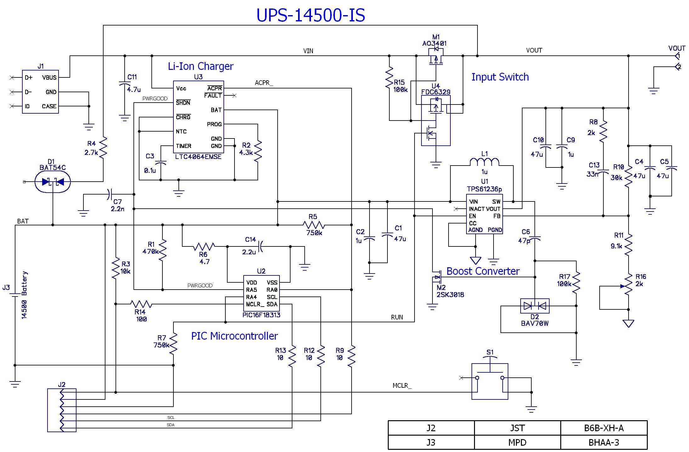
It's nearly identical to the 18650 design, but has the additional input switch circuit (U4, M1, R15) and the battery charger current is lowered to 350mA, which is the battery C/2, with a 3 hour safety timer (changes to R2 and C3). I will describe the other changes after covering the INACT pin fix.
Five components were added to fix the PWRGOOD signal function -- C6, R17, D2, M2 and C7. When the wall wart is providing power the booster is not switching and the SW pin is held at VBAT (the VIN pin potential). R17 keeps the gate of M2 at GND so it is in an off state and the PWRGOOD line is pulled high by R1, allowing the battery to be charged and the PIC to record PWRGOOD=1. When the wall wart power is removed the booster immediately begins to drive the SW pin, from 0 to 5V, at 1MHz. This action causes M2 to cycle on/off at the same rate and pulls the PWRGOOD line low after a couple of SW cycles. C7 filters out the switching frequencies and keeps the PWRGOOD line low -- even when the booster is in the low power burst mode. The purpose of D2 is to keep the gate of M2 from going too negative and keep M2 switching. D2 and M2 have to have low capacitance (2.5pF and 13pF respectively) so that the gate drive of M2 is not attenuated.
Other changes:
- Added R5 instead of using the internal weak pullup on the PIC input. This saves about 195µA.
- Changed R7 from 100k to 750k to save current. R7 is just to hold the PIC output low after reset to prevent strange behavior.
- Removed two input capacitors -- one not necessary and no room for the other. Only C1 and C2 remain on the booster input.
- Removed the 100uF output capacitor -- not necessary after testing the current UPS circuit.
- Added R4 and D1. This is a kluge circuit that injects current into the battery to compensate for the PIC current drain. The intent is to decrease the load on the battery when the wall wart is providing power and lengthen the interval between automatic battery recharges. It is more important to do this for this smaller capacity 14500 battery. This trick should increase the time between recharges by a factor of 2-5x (from 2 weeks to 1 - 2 months). Hopefully it will extend the life of the battery.
- Added the input switch. This 14500 battery won't hold up the power as long as the 18650. So there has to be some way to disconnect the power from the Raspberry Pi after it shuts itself off, otherwise the Pi could hang if the wall wart power came back on during its shutdown phase. Unfortunately the input switch causes a small voltage drop (and power loss) due to the 25-30mΩ switch resistance.
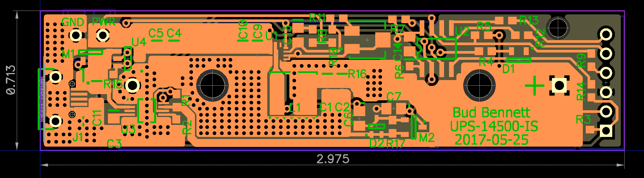
And here's the PCB layout that was sent to OSH Park to fab on 2017-05-26:
and the 3D view:
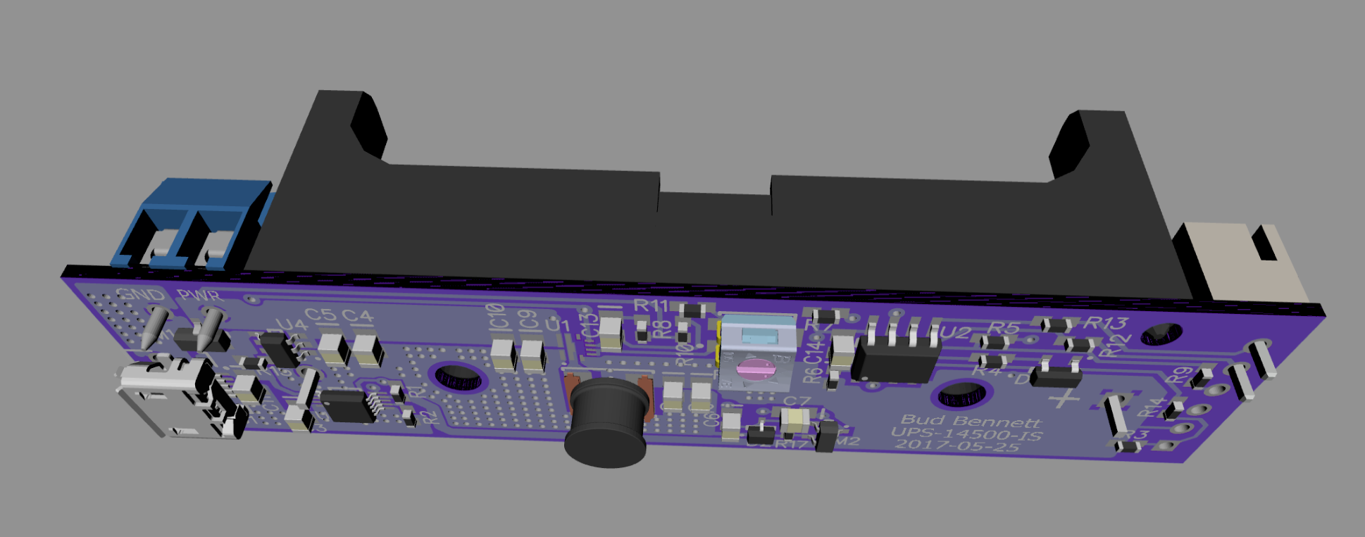
All of the circuitry fits under the battery holder. Top side components are the battery holder, output terminal block, I2C interface jack and the reset push button. This is a pretty small package -- less than 3/4"x3". The battery is equivalent to a AA battery in size. It is mounted by nylon stand-offs and screws/bolts in the two holes that go through the battery holder. I will probably use an inductor with only 2mm height instead of the 4mm inductor shown, as all of the other components are <= 2mm.
The PCBs should be back around 6/9. I'll publish the changes to the 18650 design in a subsequent log after I've finished testing this one.
Discussions
Become a Hackaday.io Member
Create an account to leave a comment. Already have an account? Log In.