 Bud Bennett
While I'm waiting for my PCBs to arrive, I thought it might be interesting to discuss the design considerations associated with the TPS61236p boost converter. This part is almost ideal for this application, though I wish that the INACT pin function was as described in the data sheet.
First of all...why the TPS61236p?...why not use the TPS61235p? Well, the TPS61235p has a fixed output voltage of 5.1VDC. This might work in a traditional UPS, but for this UPS concept having the ability to adjust the target output voltage is a big advantage. But the main attraction of the TPS61236p is the external voltage divider and the feedforward capacitor to adjust the response time of the boost converter. TI provides an application note about how to construct a feedforward compensation loop in this link. This is all well and good, but it is just a starting point. The TPS6123Xp has an internal compensation loop. TI isn't telling much about what the loop parameters are so they think they know best. They have an application in mind (probably some customer that is buying many millions of these things) and the rest of us can fend for ourselves.
Part of my experience was designing automotive circuits. There was almost no way that a 1megΩ resistor was going to be used in that environment unless the assembled PCB was conformally coated to prevent dirt/dust/humidity or other junk from compromising the resistor value. I'm using 30kΩ as a feedback resistor...so TI's suggested 10pF feedforward cap is just a starting point.
I discovered that TI offers a webpage that can simulate a TPS6123Xp application. If you click on the "simulate now" button at the lower right of the page it will transport you to their simulation environment. I found the simulation clunky and slow, but there was no other simulation option since TI did not make the TPS61236p model available for simulation on my desktop at home. I was able to setup my intended application and then adjust some of the component values to see what the impact was to the output voltage glitch (or droop) when the booster had to take over providing output power. I won't bore you with the entire process, but here's a couple of data points along the way:
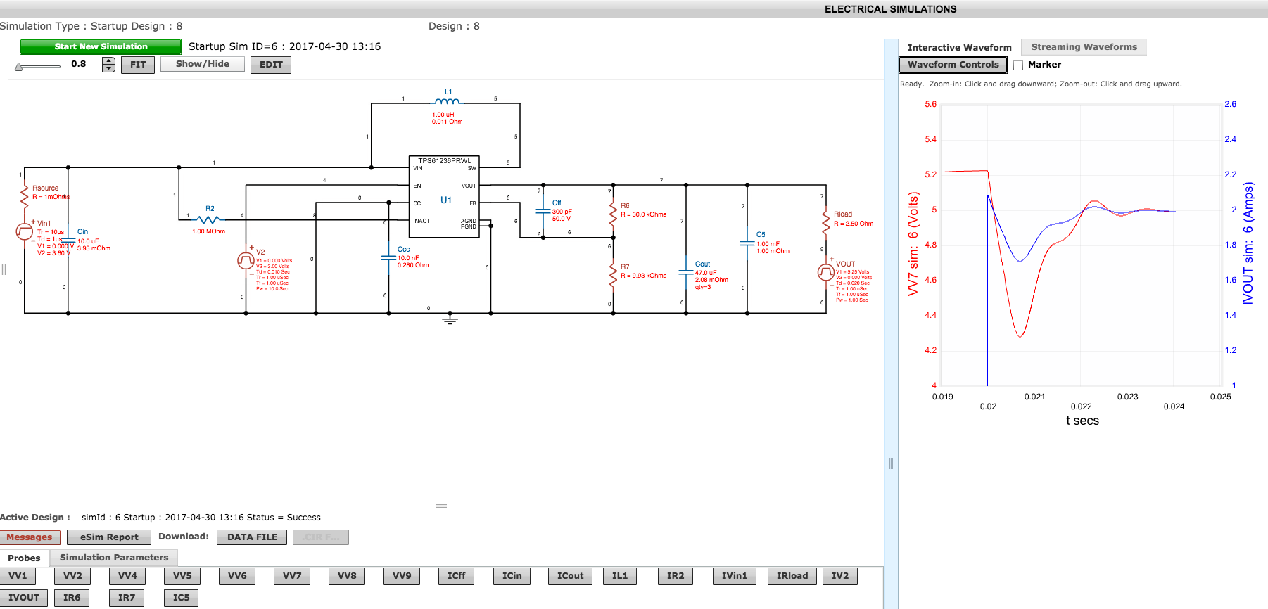
The above screen shot shows my starting point. I was using a resistor divider 30x lower than what TI suggested, so I thought that a 300pF feedforward cap might be a good place to begin. The booster target voltage is 5.00V. The output load switches from being held at 5.25V, which keeps the booster off, to a 2A resistive load. Note the waveforms to the right -- the output droops to 4.3V, which would definitely reset the Raspberry Pi. And...the bit of oscillation afterward indicated that the system was barely stable.
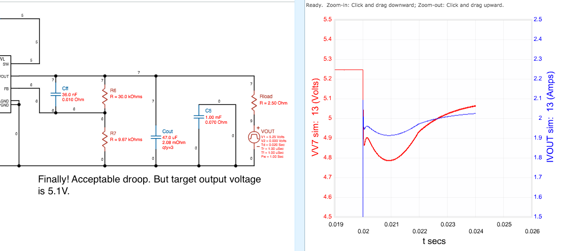
The above screen shot is near the end of the journey. I kept increasing the feedforward cap until I got acceptable droop -- in this case 200mV -- but I had to adjust the booster target voltage to 5.1V as a consequence. There is also a noticeable "long tail" response that is indicative of a right-half-plane zero. So I thought that I would insert a resistor in series with the feedforward capacitor to try to alleviate the RHP zero response. The result of that is shown below.
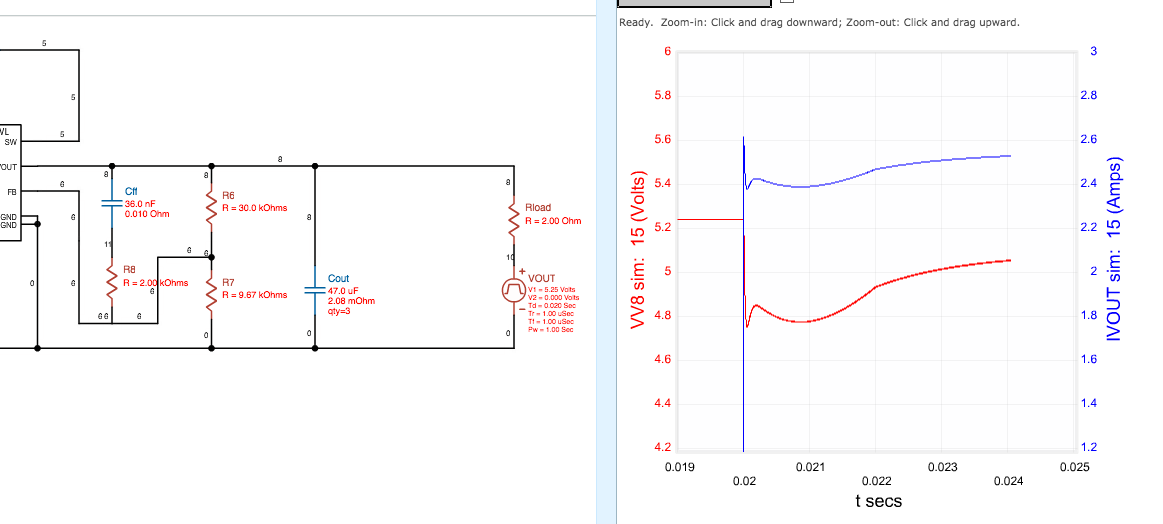
The effect of adding R8 in the simulation was not significant, but it wasn't a step backward either. I decided that this was "good enough" at this point and called it quits. I left the series resistor in the schematic as a CYA -- another variable to play with in case things did not go as planned.
The takeaway from this little bit of analysis is that without the feedforward capacitor, which is only available by using the TPS61236p chip, the output droop when the booster takes over providing power would probably reset the Raspberry Pi. Therefore, the only option was to use the TPS61236p and not the TPS61235p.
Since I don't have a 36nF ceramic capacitor in my inventory I specified a 33nF for the initial design. When I built the PCB I populated a zero Ω resistor in series with Cff (C13 on my schematic). After looking at the scope traces from the switchover events, this seems to be a good choice for the feedforward capacitor/resistor going forward.
Discussions
Become a Hackaday.io Member
Create an account to leave a comment. Already have an account? Log In.