 Bud Bennett
Some gremlin let the magic out of board #1. When I let the UPS charge the battery deep into the constant voltage phase the charger proceeded to overcharge the battery again. So the oscilloscope came out of storage and the hunt began. I'm seriously thinking that MSOP packages are not in my future. Here are the fixes that I made to both boards to get them working:
- I could not get the LTC4064 charging on board #2, so I replaced it with a recycled one from a previous revision. It still would not charge reliably (i.e. more than once). It turned out that some of the pins on one side were floating slightly above the board. When I checked them for connectivity the pressure from the probe caused them to sit on the pads and they looked good, but after the measurement they bounce back off the pad. I found the problem by rolling my fingernail over the tops of the pins and the charger started working. It seems like these MSOP parts either have too much or too little solder. Not great for hobbyists.
- The LTC4064 exhibited a bit of weirdness in the regulator loop. The PROG pin would occasionally jump from the normal 1.5V to about 2.2V and stick there -- this was what was causing the overcharging. (I think) it was fixed by increasing the bypass capacitor, C11, from 4.7µF to 10µF.
- Increased C7 to 47nF. The charger/booster race condition was still there when I checked the PWRGOOD signal with the scope. I had a 47Ω load on the UPS. If the wall wart was initially plugged in then everything worked and the battery was charged. If the wall wart was unplugged and replugged then the charger would not charge the battery. The scope trace showed a 2Vp-p sawtooth at PWRGOOD. The PIC did not care since it was set to have Schmidt-trigger input levels. But the charger has a shutdown threshold of around 1V and it was being toggled at a high rate. The 47nF allowed the PWRGOOD signal to ride through the transient produced by the booster.
- Changed R14 on board #1 to 0Ω and can now program the PIC in the circuit.
So now there are two working UPS-14500-IS units. I did connect one of them to the Raspberry Pi 2 (with a 16GB thumb drive and wifi adapter attached). It kept the power to Pi without any issues. I did not run any load tests and the Pi was essentially idling. The UPS held the power up for 1 hour 26 minutes! It also recharged the battery back to full in about 2 hours, as expected. I can't measure the safety timer but the timer's oscillator was still running 4 hours after it started charging, which is probably normal. The only problem I had was when I tried to use the push button to turn off the power to the Pi after issuing a "sudo poweroff" and unplugging the wall wart -- I had to keep the push button pressed for at least 5 seconds or the UPS would restart the Pi. I think that the wall wart has a large output capacitor that holds the input voltage to the UPS above 4V for a long time. The 5 second button press allows it to discharge enough that the UPS doesn't think that there is AC present.
I measured 42mV across the input switch when it was holding up a 1.25A load, so that puts the switch resistance at around 32mΩ.
The final tests are to see the size of the voltage droop when the wall wart loses power. I ran two cases:
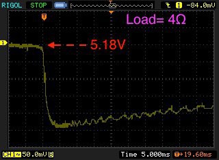
The above trace shows the output voltage droop when holding up a 4Ω load. The UPS output voltage, when powered by the wall wart, was 5.18V. The booster target voltage is set to 4.99V. The UPS allows the voltage to drop to about 4.94V before it catches it.
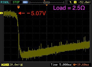
This trace is the same test with a 2.5Ω load (about 2Amps). The UPS output is now 5.07V, when powered by the wall wart. Some of that is due to the voltage drop across the input switch. The booster target is 4.99V. The UPS catches VOUT at 4.94V again. That's pretty good for a battery with nearly 0.4Ω of internal resistance.
At this point I'm satisfied with the performance of this board and calling it a wrap. It is doing everything I need it to do. I now need to code the routine that services the UPS in the background. Time to move on to the 18650 version, and possibly the "Hat".
Discussions
Become a Hackaday.io Member
Create an account to leave a comment. Already have an account? Log In.