 Bud Bennett
OK, I'll admit it right up front...I stole the idea to hang the battery upside-down off of the Raspberry Pi header from Patrick Van Oosterwijck's LiFePo4wered/Pi+ project on Hackaday. Everything else is an extension of this ongoing project.
PaulV and I have been going back and forth about this Hat concept for quite a while. I'm not really enthusiastic because some of my headless Pi systems have very sensitive electronics hanging off the header, and so placing a 1MHz multi-Ampere switching regulator nearby is not high on my list. It would be OK if the system was not required to keep operating normally (like my heating system), but my seismometer must keep going as if nothing happened, so I'll be using the 18650 UPS for the seismometer and placing it reasonably far away from the sensing electronics and most probably shielding the UPS as well.
It is called "Hat-like" because there is no EEPROM on board to make it a true "Hat".
The physical nature of this UPS is its most important feature so I will start out with the 3D view.
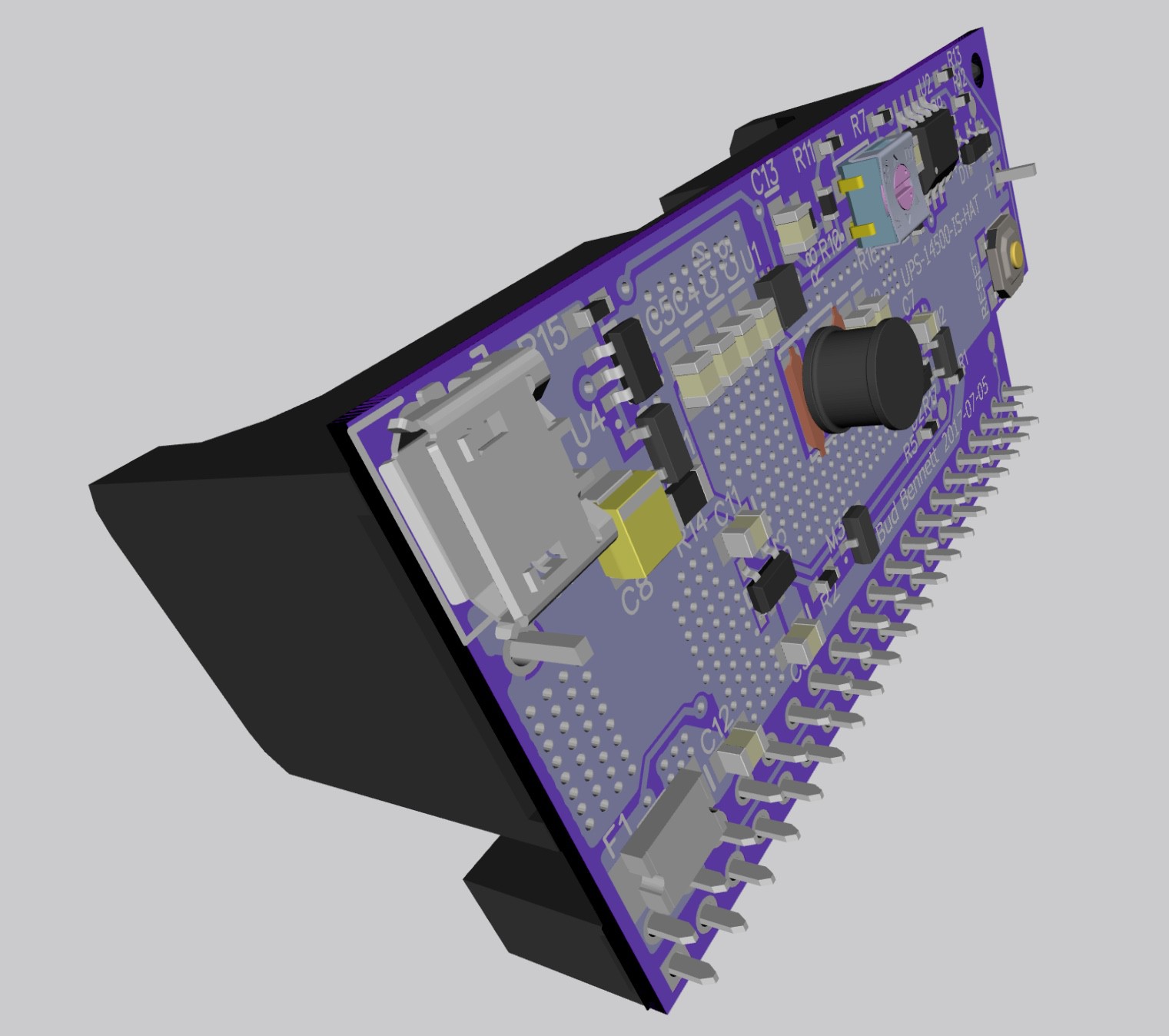
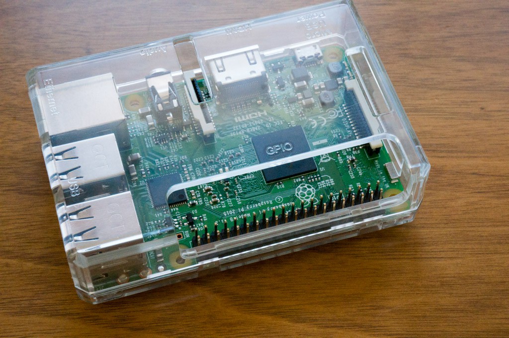
The header jack and battery holder are the only items placed on the bottom of the board. It is designed to work with the type of case shown below. It probably won't fit the Official Raspberry Pi case because there is a maximum distance of 4.5mm from the header to the battery holder, which is not enough clearance for the larger case style. I want to keep that spacing short to avoid putting too much stress on the header which will be the only thing supporting the UPS. Of course it would also work without a case, if the Pi was mounted to a surface with stand-offs.
The layout view should be considered next. Most of circuitry was directly ported from the UPS-14500-IS design. There are a few important considerations:
- The microUSB jack should probably be located to the left of the board so that the power cable doesn't interfere with the other ports of the Raspberry Pi.
- The push button reset switch had to be move to the top-side of the board for easy access.
- Because there are only two components on the bottom side of the board the goal was to make it no larger than required to support those components. As a result this PCB is a bit shorter, but wider, than the other 14500 UPS version. I believe that it is as small as possible.
- The two holes used for mounting the board through the battery holder are not required, and therefore deleted to make room for better bus width or component location.
- There is a cutout on the lower right to allow use with the planned case types.
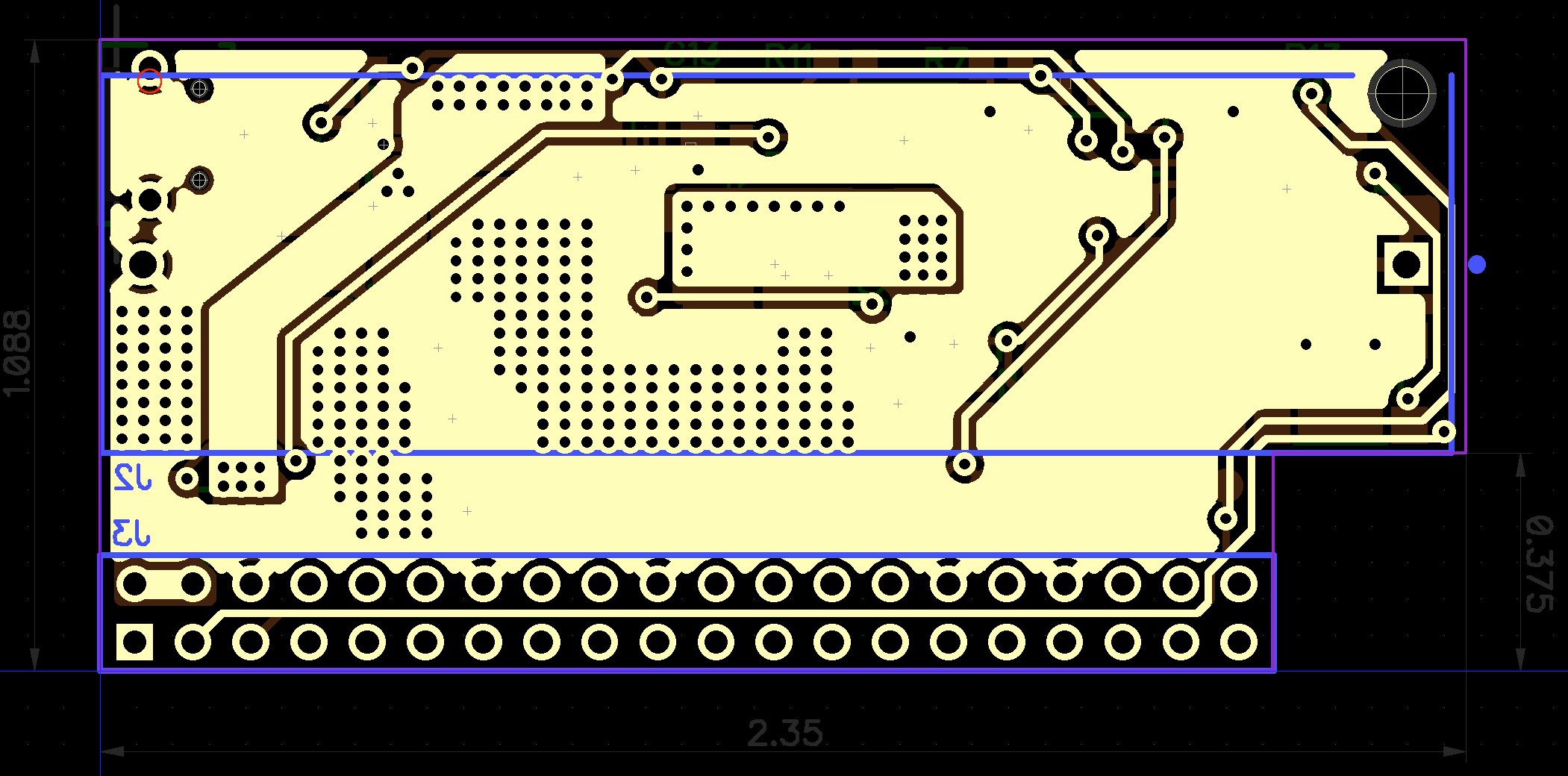
There were some tradeoffs that had to be made. Note the VIN trace that cuts diagonally from the upper left corner of the board. It must cross the top side GND plane, which had to be compensated with lots of via hole to the bottom side GND plane.
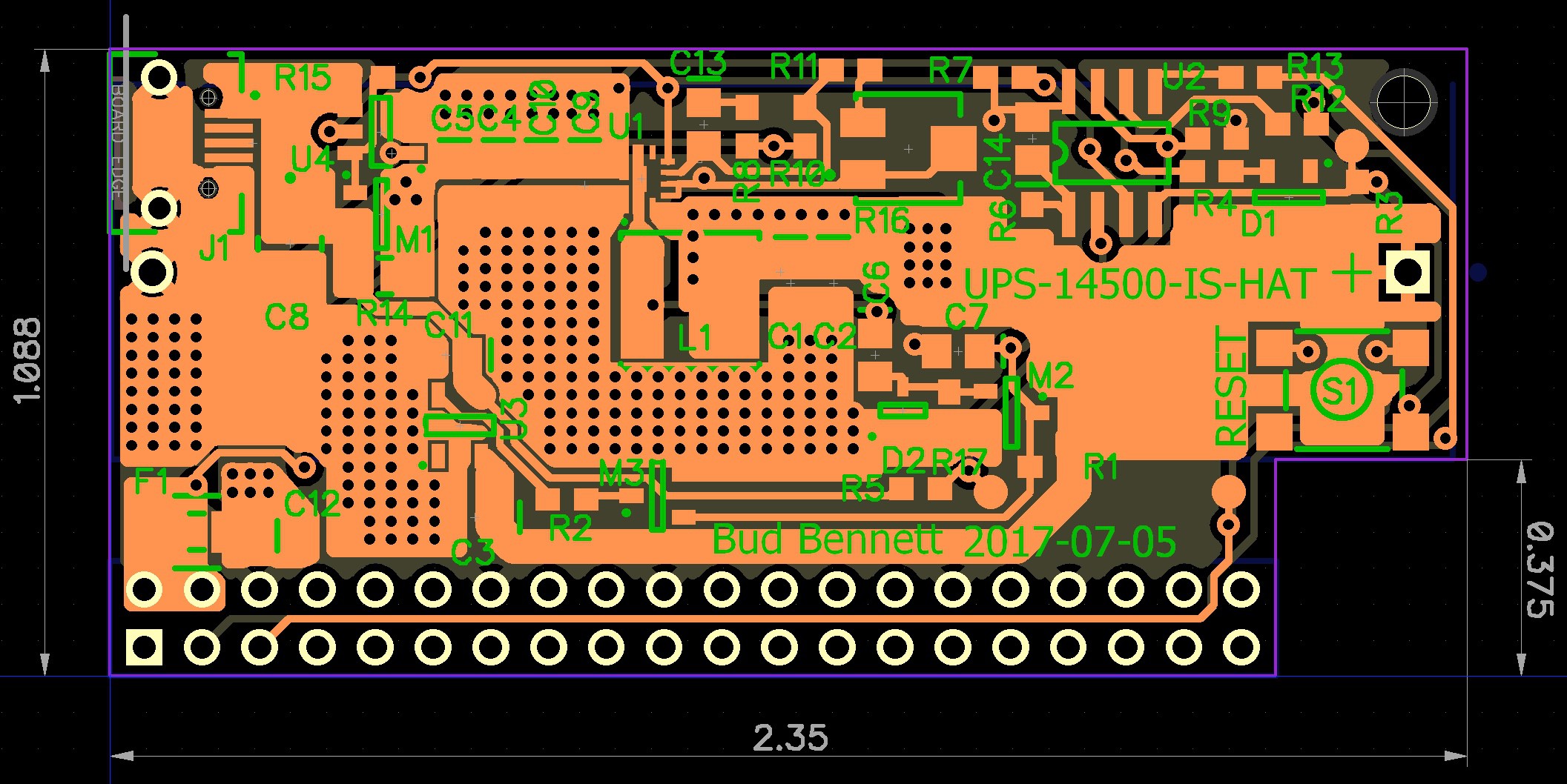
The bottom side also has a wide trace cutting across the board to connect VOUT to the header +5V pins. This time the top side GND plane was used to jumper over that trace to keep the GND resistance low. The trace widths are probably much larger than needed, but it generally pays dividends to be conservative in that area. There aren't any critical components on the right quarter of the board so the GND plane in that area is almost a don't care. Note that the PCB could be smaller along the top edge, but that battery holder locator hole at the top right needs to be surrounded by the board.
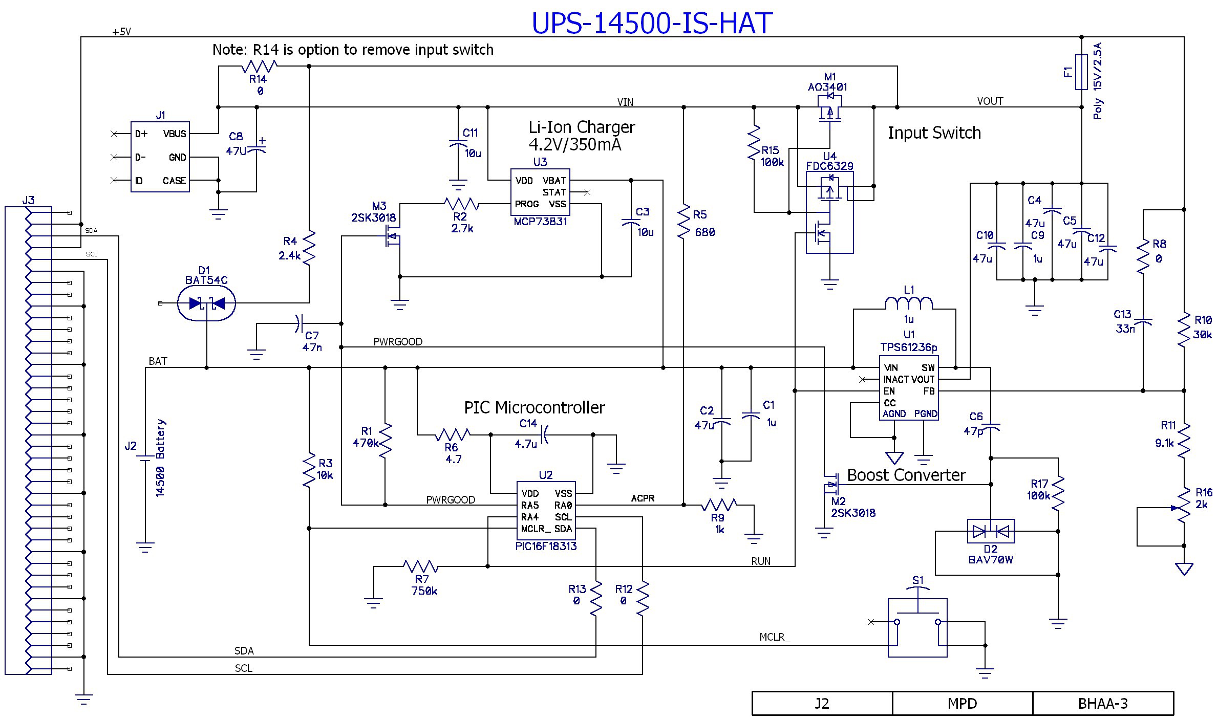
Schematic Changes:
- The LTC4064 is gone. In its place is the MCP73831/2. This new charger part doesn't have a safety timer, and charges the battery to a 4.2 termination voltage, but it is one heck of a lot simpler to handle. One of it's package options is a SOT23-5 for about $0.60 each from Digikey.
- The MCP73831 doesn't have a dedicated shutdown input, so another 2SK3018 NCH FET was added to open the programming resistor and set the charging current to zero, effectively implementing a charger shutdown.
- Since the battery charger is no longer providing an AC present indicator signal the PIC will need to be reconfigured to do it instead. R5 and R9 divide the VIN voltage down to and acceptable range for the PIC. (The PIC has a comparator block that could be used for this function, but it is probably overkill and higher current draw, so it will be plan B. Plan A is to just use the Schmidt Trigger or TTL inputs of the PIC.)
- R14 is a 1206 jumper resistor (zero Ω) that can be used to disable or remove the input switch. After getting nearly 1.5hrs of operation on a lightly loaded Raspberry Pi, it seems like an appropriate option to implement.
- The layout can accommodate either a 6V/2A 1206 poly fuse or a 15V/2.5A 1812 poly fuse because the power would be applied via the RPi header instead of the microUSB input.
- There was room on the layout to add C8 across the microUSB input. And C3 was added as a precaution to increase the stability of the battery charger when in constant voltage mode.
Here's the latest schematic that matches the layout above:
Discussions
Become a Hackaday.io Member
Create an account to leave a comment. Already have an account? Log In.