 Pascal Roobrouck
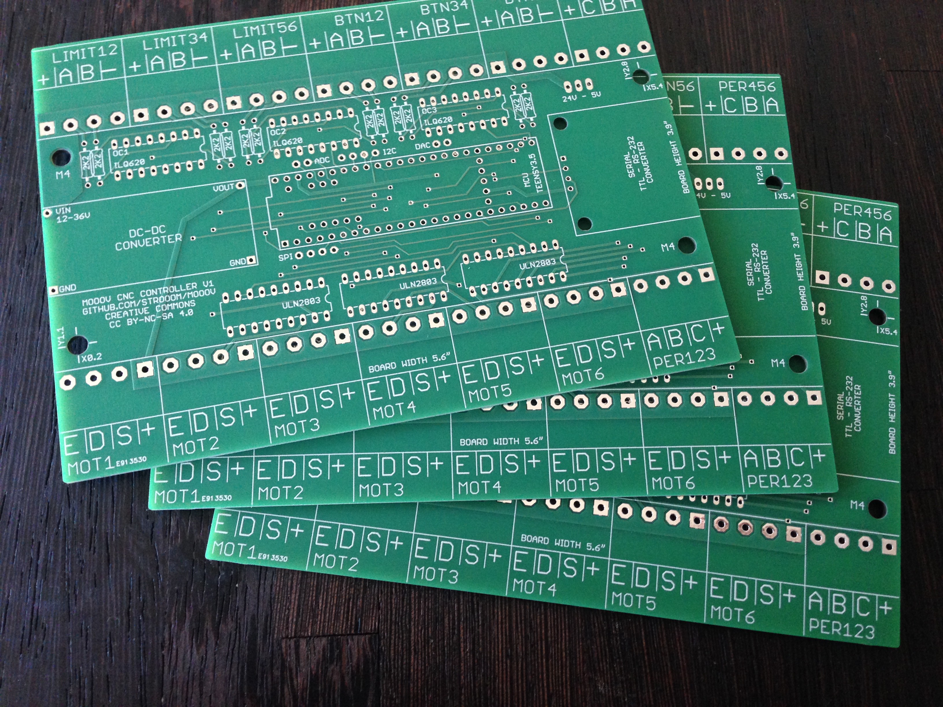
Connecting the Teensy to (up to) 6 Motor Drivers, (up to) 6 peripherals Solid State Relays and (up to) 12 input switches, involves a lot of wiring. Furthermore all inputs are opto-coupled and all outputs are open-collector drivers, allowing any type of motor drivers to be used.
So I decided to design a PCB to keep al this clean. Turns out I needed about 100 * 140 mm.
PCB was designed in Autodesk Eagle, schematics and layout files are available on Github.
During assembly I noticesd a few mistakes : basically the serial port and USB port connector are hard to reach because other components are obstructing it. This will need to be solved in the next version.
I had the PCB manufactured at Euro-Circuits.
Discussions
Become a Hackaday.io Member
Create an account to leave a comment. Already have an account? Log In.