This project pretty much worked in reverse from how one would normally do a design. Normally, you'd select the processor (and other hardware) based on the required functionality. In this case, I had some spare processors and so defined the functionality to match the hardware limitations.
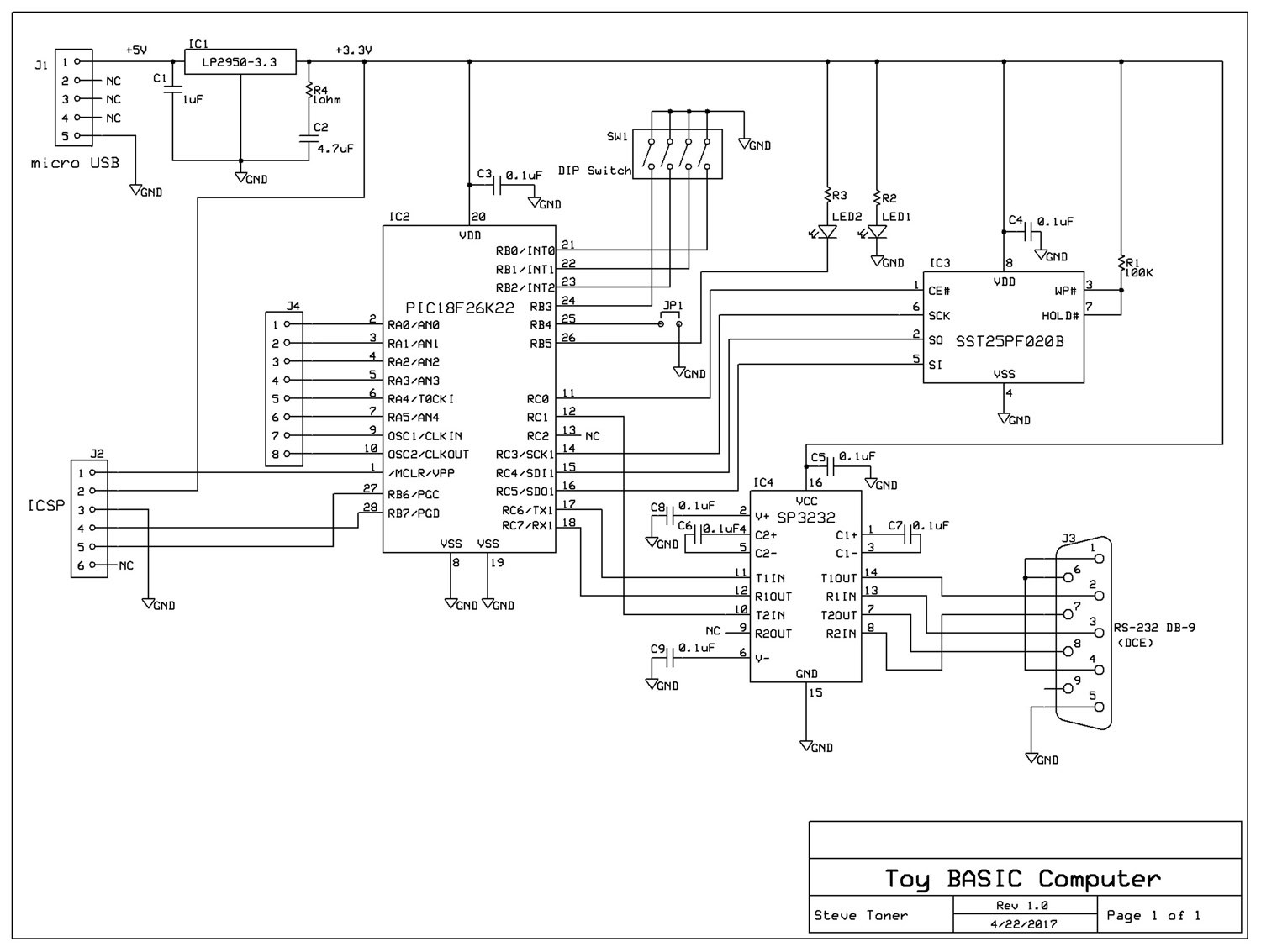
The schematic is quite simple & straightforward. Note that the PIC's PORT A is unused (shown connected to J4 in the schematic), so could be used for digital input or output if someone wanted to add appropriate statement code.
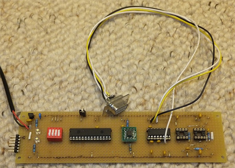
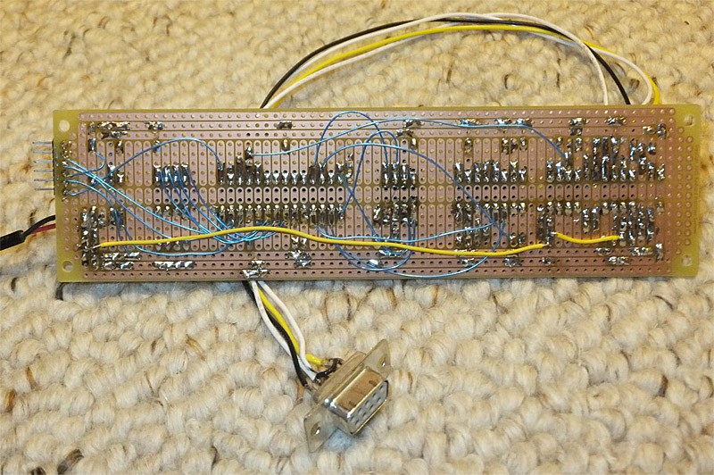
The PCB is laid out with ExpressPCB, using their MiniBoard service. I have Eagle, I could have used it & made the PCB smaller and cheaper to buy in small quantities, but I hate it so I only use it when I have to (i.e., someone is paying me to use it). It uses a mixture of surface mount and trough-hole parts. The ICs are all surface mount with the exception of the voltage regulator. That's mostly because I had some TO-92 regulators on hand, so it saved a few cents in parts cost.
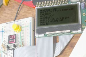
The PDF file has the documentation for the project, including the details of the dialect of BASIC that it supports. Note that I did NOT use Tiny BASIC, which seems to be very popular for projects of this nature. It's a complete, from-scratch implementation designed to make maximum use of the limited RAM in the PIC processor.
Source code is in the ZIP file. It is licensed under GPLv3.0
 svofski
 jimshortz
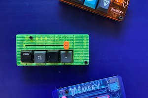
 ZenVega