 Frank Buss
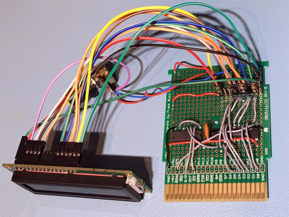
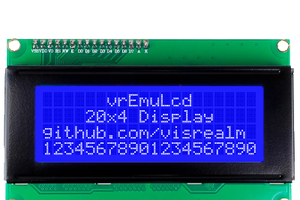
I saw a video from The 8-Bit Guy, where he demonstrated a LCD display on the user port of the C64. But it can be done on the expansion port as well. This project shows how to do this, with my C64 cart-proto board.
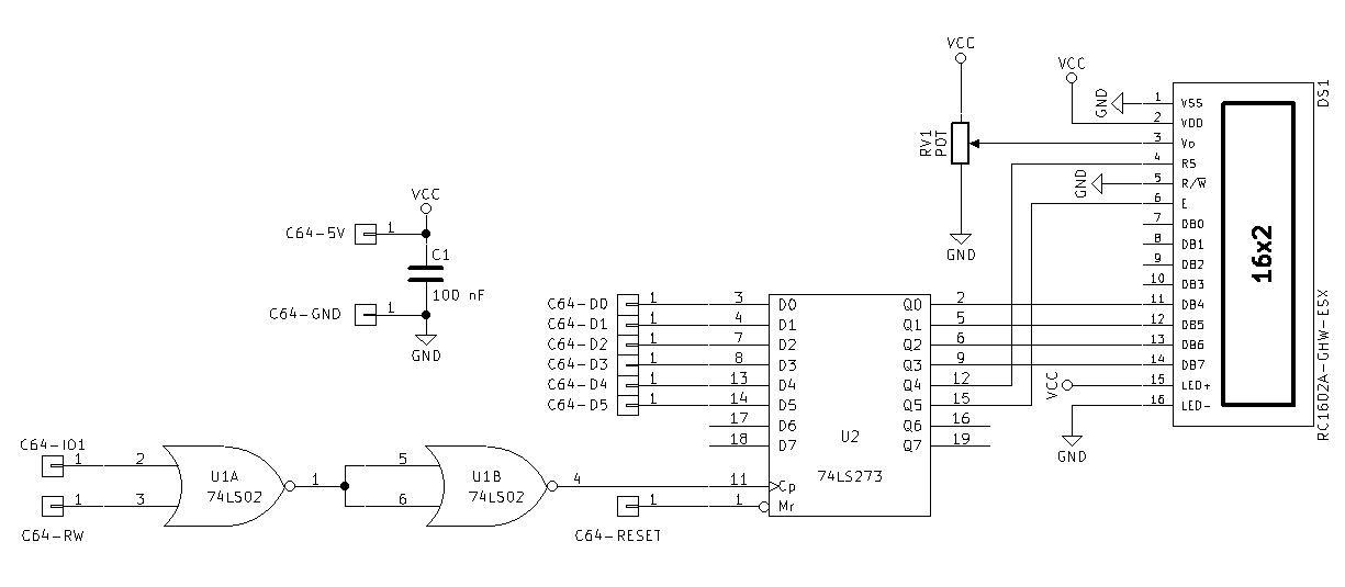
Unlike the user port of the C64, it is more difficult to use the expansion port, because you don't have a stable parallel output, but the data bus of the 6510 is routed to the pins of this port, which changes all the time when data is written to the RAM etc. But fortunately there are other signals like IO1, which goes low whenever you read or write something to $DE00-$DEFF. Together with a latch, you can save the byte that is written to it, so that you have 8 extra stable parallel out signals. I do this with some NOR gates, see the project log for details. This can be easily enhanced, e.g. use the IO2 signal for $DF00-$DFFF for a second latch, so that you then have 16 output signals. Or latch it on read with some more gates for some input signals.


 Troy Schrapel
 ElecLab
 alcor6502
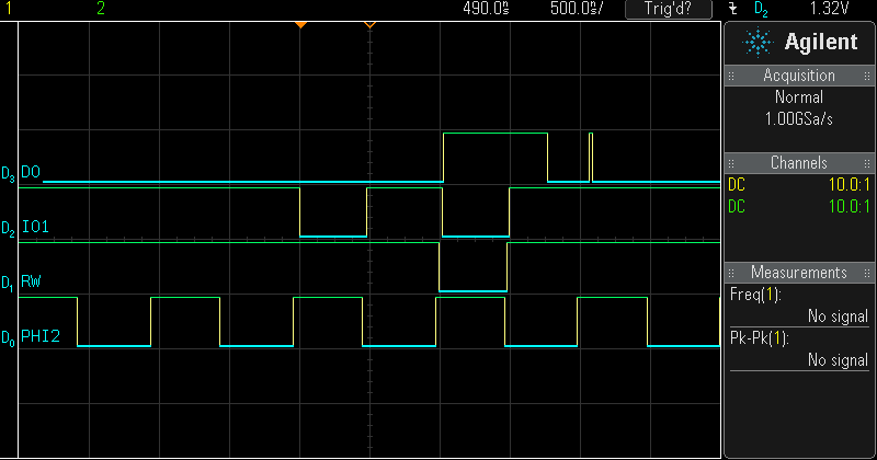
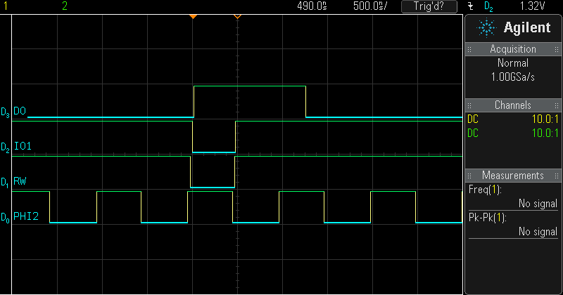
Hi Frank your oscilloscope shows 74LS02 "NOR" device combining IO1 "and" RW for latch enable of the 74LS273. However your schematic [NOT (IO1 NOR RW)] is actually IO1 "or" RW. It would be a slightly different configuration of that NOR device to make logical "and". I think your wiring might be a "NAND" device instead of "NOR".