So the idea of using a pico projector as a maskless lithography system seems sensible, except for one minor problem. Projectors making small images big, and we want the opposite. We need to convert the projector into a microscope-projector.
The first order of business is to remove the projection lens, which removes the vast majority of the image enlargement. If we revisit and annotate an image from the LCos Light Engine log entry, you can see that there are still a few hiccups to work around:
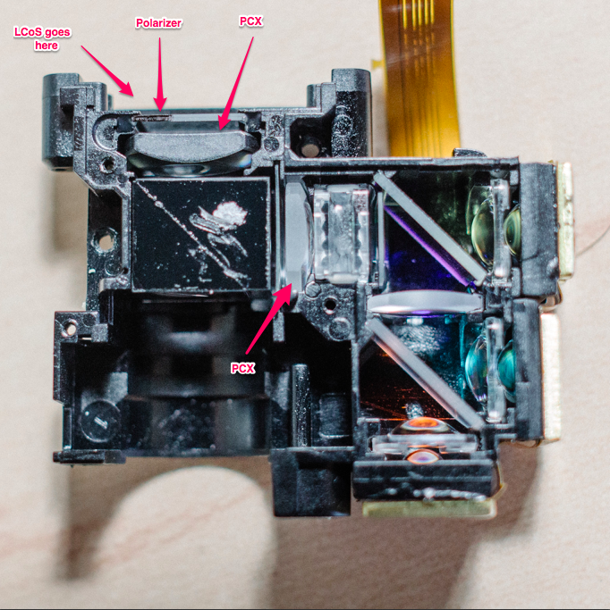
Because the illumination source is derived from a diverging light source (e.g. LEDs), the light cone needs to be focused onto the LCoS. This is accomplished with two Plano-Convex lenses, which act as condensers.
Unfortunately, if the light is being focused on the LCoS, that means it diverges when it exits the beam splitter. Of course, this is exactly what you want in a projector, but we need to find a way to shrink that image back down.
I debated pulling out one or both of the PCX lenses, but they are cemented in pretty well and I didn't want to scratch them, in case I had to put the lenses back in. So I got to work building an optical train to reduce the image.
De-magnifying the image
I have a 60x microscope objective that I was intending to use for this project. The idea was to focus the projector's light down to the right size/focal length so that the microscope objective could do the rest of the work.
This proved very difficult, unfortunately. My objective doesn't state it's tube length so I'm not sure exactly what kind of focal length is required to feed it. And collecting enough light from the projector has proven very difficult. You need either very short focal length lenses close to the LCoS, or much larger lenses farther out to catch all the light cone as it diverges.
Someone who knows optics would just sit down and do the math to figure out what's needed. That person is not me, unfortunately. So I just started fiddling with the various lenses at my disposal.
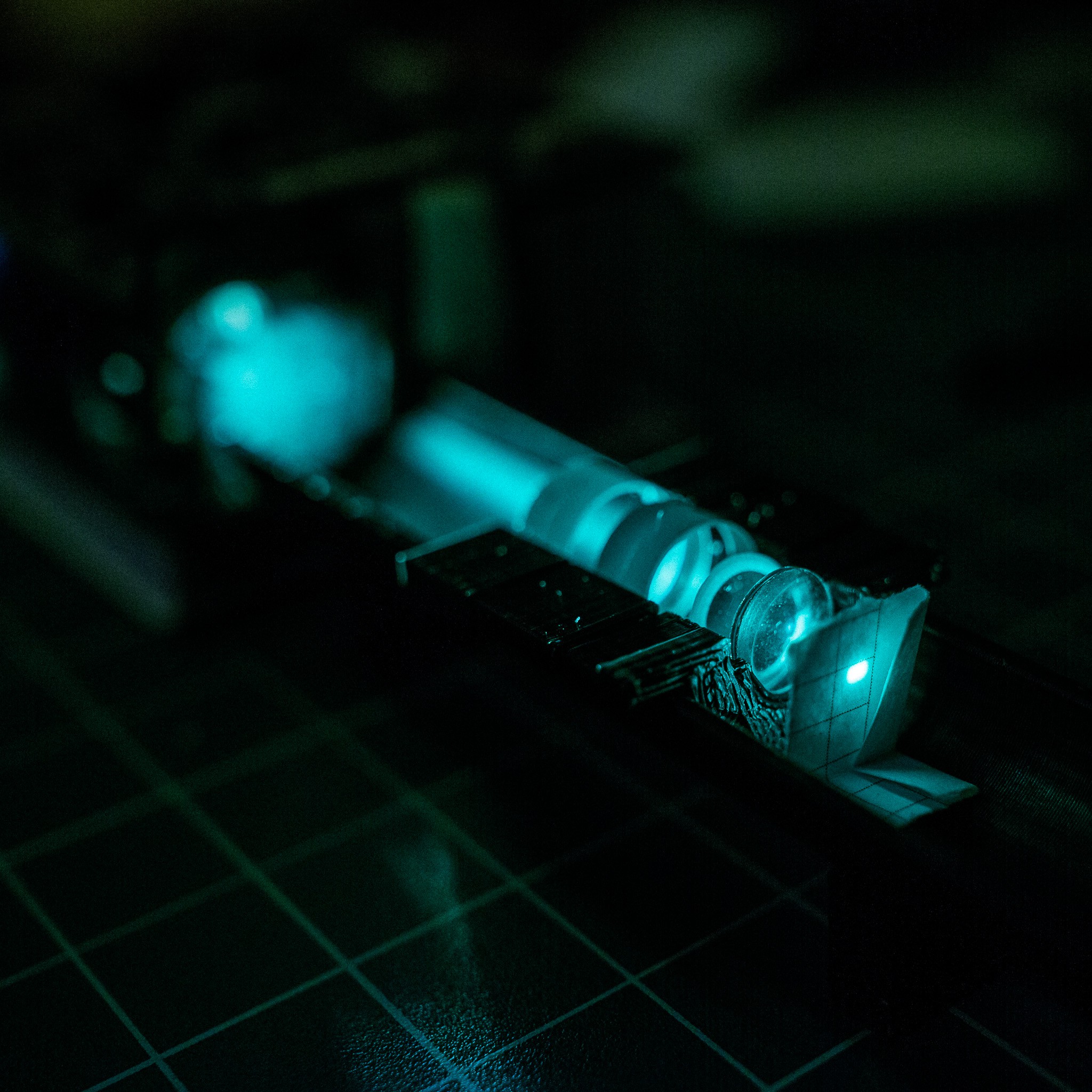
During the course of haphazardly fiddling, I realized that I had accidentally re-created a poor-man's achromat compound microscope objective. It focuses the light down to ~1mm rectangle.
I think I may just stick with this setup, rather than attempting to shoehorn a real objective in there (at least for the first prototype).
So what does it look like?
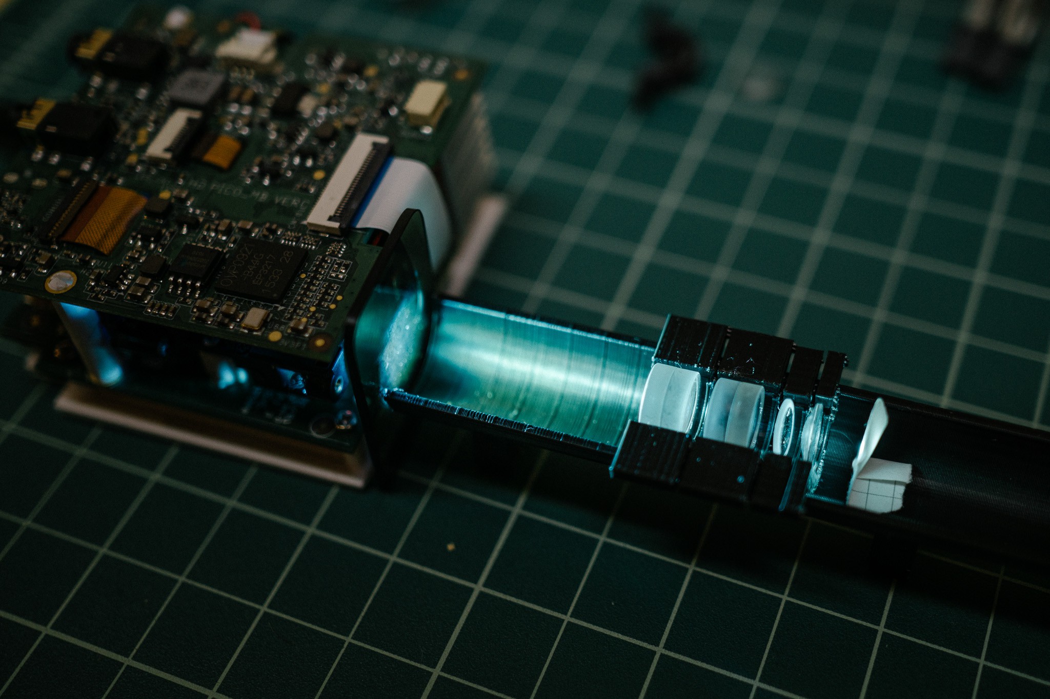
You can see the pico projector on the left. In front of the light path is a dark plate; that's a neutral density filter. The projector is not very bright relative to "real" projectors, shining a paltry 25 lumens. But 25 lumens focused to a single spot is still very bright to look at, and difficult to focus manually. The ND filter helps cut the output so it's more manageable to look at.
Then there's that black sushi-boat looking thing. What's that? It's an optical bench, but no, not the fancy optical bench I designed. As it turns out, I needed to position the lenses very closely together, and the bench I designed requires ~1cm between lenses due to the thickness of the holders. Oops.
So this is a simple print which is essentially a cylindrical boat. Lenses are placed inside little holders with varying sizes to accommodate different lens diameters.
Then there's the lens stack. It looks like:
- Achromat
- Achromat
- Positive Meniscus
- Plano-Convex
- Paper target
If you look at how achromat objectives are built (source):
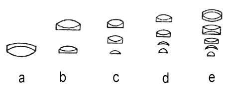
You can see that it's very similar, albeit using a PCX instead of a hemispherical lens at the bottom.
A quick raytrace looks something like this (with entirely made up lens parameters, these aren't the same as my actual lens... just for demonstration):
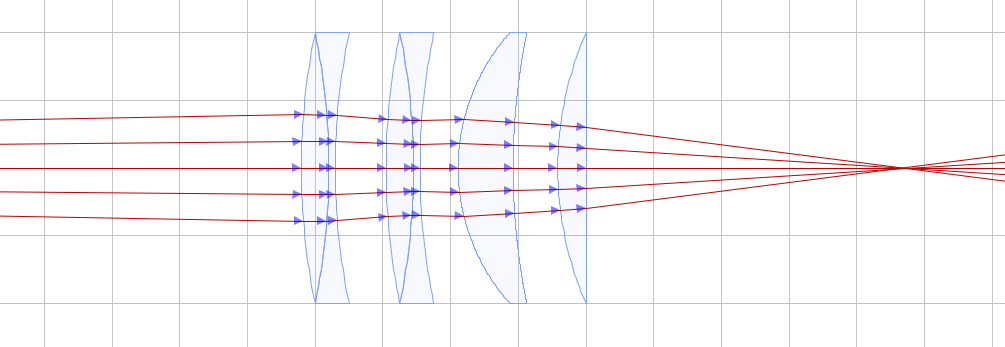 I ran the numbers on the compound lens and think it is basically a 11x objective :D
- 11x magnification
- 0.66 NA
- 3.9mm focal length
- Projected dimensions: ~0.85mm x 0.43mm
- Projector resolution: 1280x720
- Theoretical min feature size: ~0.67µm
*With the caveat that optics is entirely new to me, so I may have messed up the equations :)
405nm light is limited to ~606nm feature size anyway, so that's certainly good enough for me! In reality, I expect it to be several times greater than 0.67µm. There's vibration to deal with, I'm sure I have terrible spherical aberration from that PCX lens at the end of the stack, focusing is going to be difficult, process difficulties, etc.
Still, I'm rather happy how it turned out, given I know nothing about optics. :)
The next step is to incorporate a beam splitter somewhere so I can use a camera to help position, and to figure out how best to replace the LEDs with a laser (or maybe just bigger LEDs).
Fun aside
Amusingly, when trying to take photos of the setup I noticed this weird chromatic effect in my camera:
It was noticeable in the live preview, and even more in the video. What's going on? Have I created some fantastical machine which slows down light so much you can see it shift colors?
Nah :)
Cheap (and small) LCoS projectors like mine use a single LCoS chip, unlike more expensive ones which have a chip-per-color. That means the colors are actually being shown sequentially; turn on the first LED, display the pattern on the LCoS for that color, switching to the next LED, etc etc.
Apparently, the frame-rate on my camera was juuust righ to catch this in action, and create the effect of slow-moving chromatic changes. It's similar to the optical illusion of seeing wheels "spin backwards" when they are rotating fast enough.
Pretty fun to watch though :)
 polyfractal
Discussions
Become a Hackaday.io Member
Create an account to leave a comment. Already have an account? Log In.