 MakersBox
-
An Unfortunate Mask
07/27/2017 at 04:34 • 1 commentI think I have confessed elsewhere that the only way I was able to complete this unfortunate project was to cheat by using solder mask. This allows you to spread solder paste only on the pad areas, and capillary action will actually pull the piece in to place as the paste melts in an over or over a hot plate. It is quite a thing to witness.
There are two ways to get a stencil. Once is to use a laser cutter. Most of us, including me, do not have a laser cutter in our garage. You may have a friend or Maker Space you can use. Most laser use SVG files, which you can find in the files section.
For the rest of us pour unfortunate souls, you can cast your mercy on someone like OSH Stencils, who will take your money to easy your misery. The gerber plot file is also in the files section. I would use a 3mil polyimide and 0.75" boarder. This should cost your about $5.00.
![]()
[Update] OSH Stencils has provide a link for ordering.
-
An Unfortunate Kit
07/25/2017 at 01:05 • 2 commentsSo, my original intent was always to make a "Gentle Introduction to Surface Mount Soldering". This project became the alter-ego of that one. They actually share quite a bit of hardware and software, so I figured if I was going to kit one, I might as well as spread the misery and kit this one as well. Don't think I am doing you a favor. I will regret it, I'm sure:
https://www.tindie.com/products/MakersBox/smd-challenge/
![]()
Here is the other project, which is happy, well documented, and which I will gladly sell you:
https://www.tindie.com/products/MakersBox/i-can-surface-mount-solder/
![]()
-
Programming Surface Mounted Chips
06/14/2017 at 02:59 • 5 commentsA majority of my projects to date have used DIP package Attiny85, 84, and Atmega328. These are usually programmed beforehand using a ISP shield on an Arduino, or afterwards using the ISP header. My first PCB design, was in fact, a shield which could be used to program the variety of AVR chips I was using. Breadboarding up an Arduino-as-ISP circuit time every time I needed one was error-prone and frustrating.
![]()
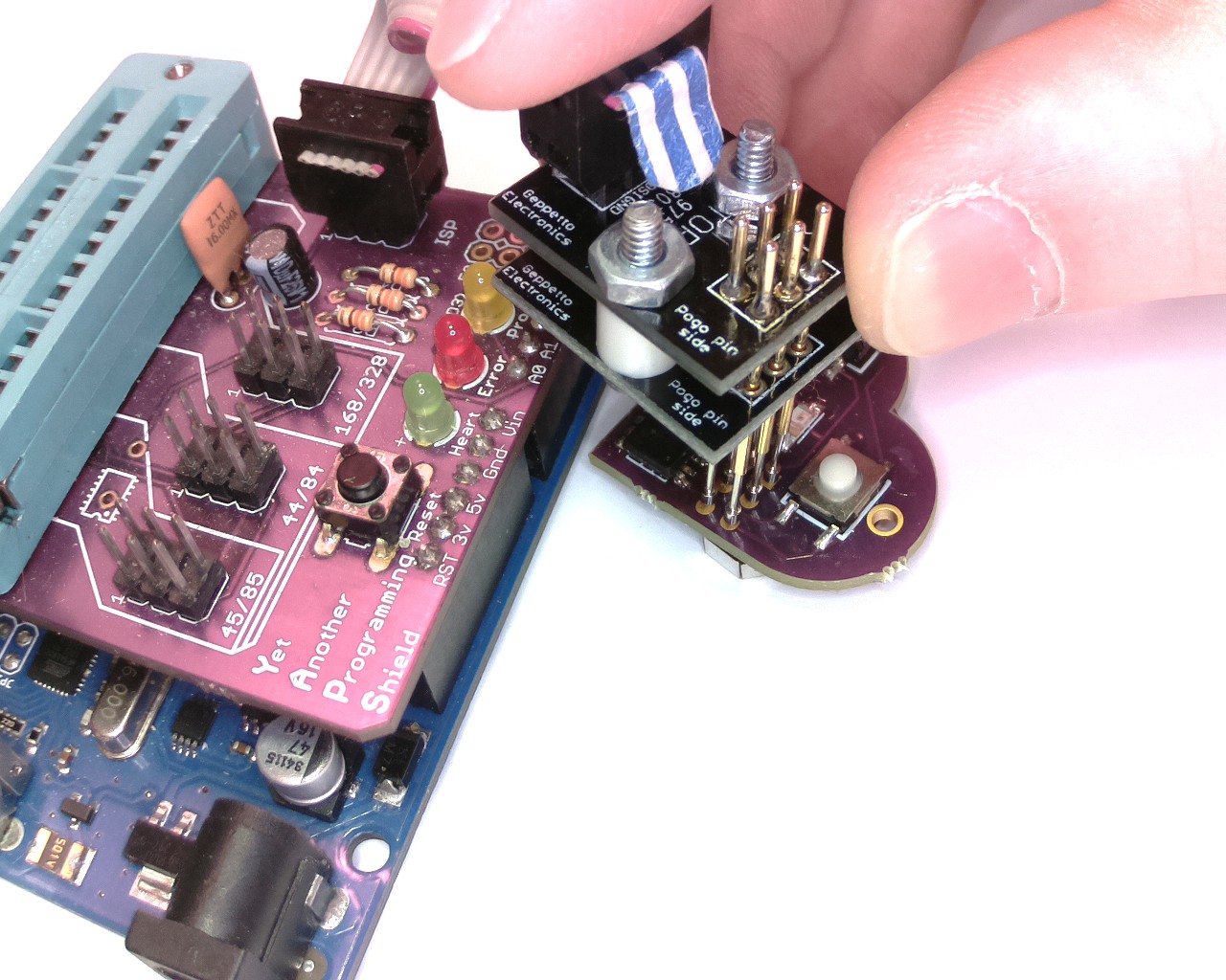
Programming via ISP header using Pogo Pins
My Making has progressed to the point that I have started doing SMT, mainly because I've been doing wearables and like the idea of having a coin cell battery on one side and the microcontroller on the other in a nice tidy package. The SOIC package is hand solderable, and using pads for the ISP header instead of through holes helps maintain the advantage of going SMT. Making a good connection to pads using a 2x3 pin header was a hit-and-miss proposition, so I was happy to find Nick Sayer's ISP Pogo Adapter.
![]()
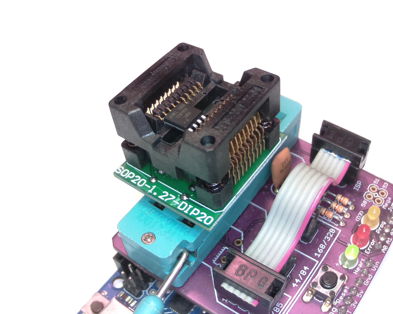
SOIC to DIP adapter installed in a ZIF socket: Turtles all the way down . . ..
It occurred to me that since not all projects have ISP headers, there should be some way to program the chips prior to installation. With a little googling, I found SOIC to DIP adapters which can be used to mate up with a DIP ZIF fixture. A SOIC 20 allows me to program the AVR 8-pin, 14-pin, and 20-pin packages!
![]()
EIAJ Flavor SOIC. Datasheets are your friend . . .
The one cavat here is to be aware that there are two types of SOIC package, a wider EIAJ version that AVR supplies, and a narrower JEDEC version (oh, why do they do this to us?). My first ebay adapter purchase was the narrow version, and this problem has bit me with PCB footprints as well. A word to the wise . . .
-
The smallest part I have ever worked with . . .
06/06/2017 at 02:32 • 5 commentsThis is my forth iteration of this project. I don't know why I punish myself.
![]()
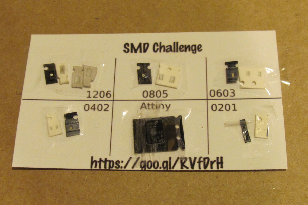
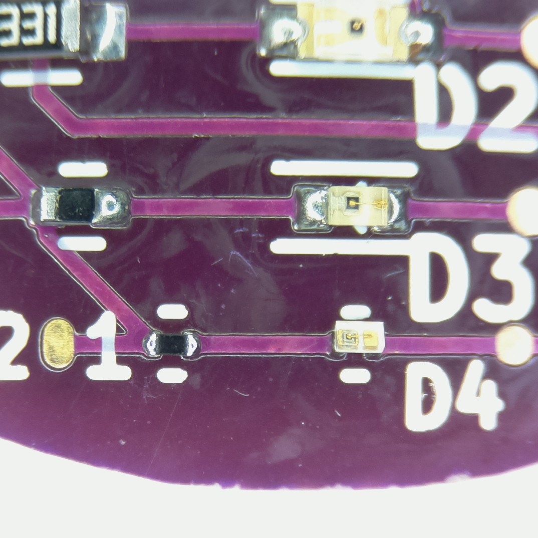
The smaller LEDs are hard to tell the orientation. They are all packaged in the same orientation with the negative side (cathode) toward the side of the tape with holes in it. They all have a "whisker" wire that point to the positive side (right in the photos).
![]()
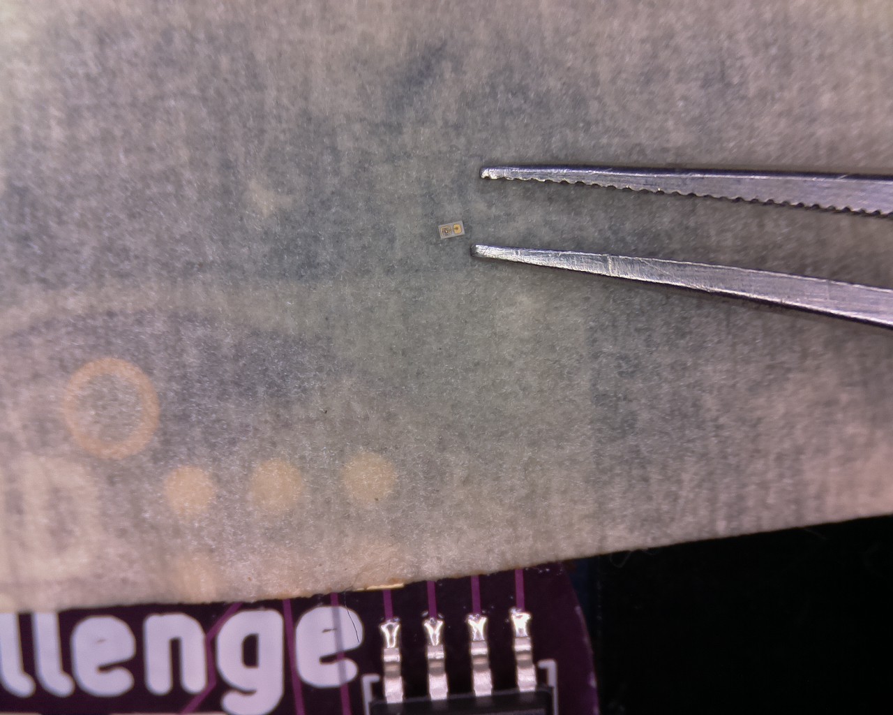
I must confess, I never even tried to hand solder the 0201 chips. I can do the 0402s by hand, but even with the thinnest of tips, I doubt you can get the 0201s to stick without cooking them. Prove me wrong.
![]()
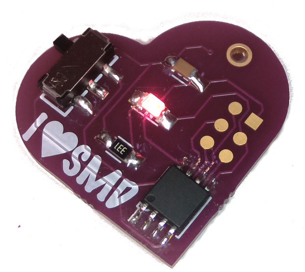
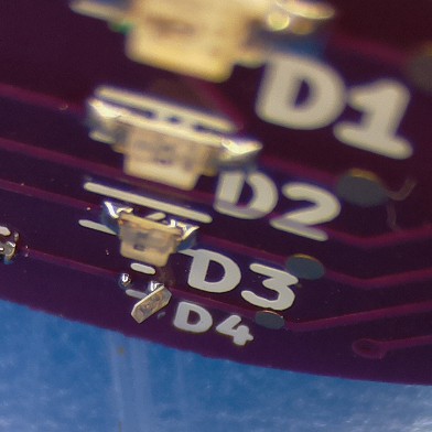
Here is my first attempt with a solder mask and hot plate. I had to pull the LED off with the iron (it basically disappeared into the solder on the tip), and then remask it. Quite frankly I'm surprised it worked. At least I proved the circuit. Now I can move on to something less unfortunate.
An Unfortunate SMD Project
If you like happy, easy to build projects, this is not for you. This project is only for people who like to be miserable and frustrated.
