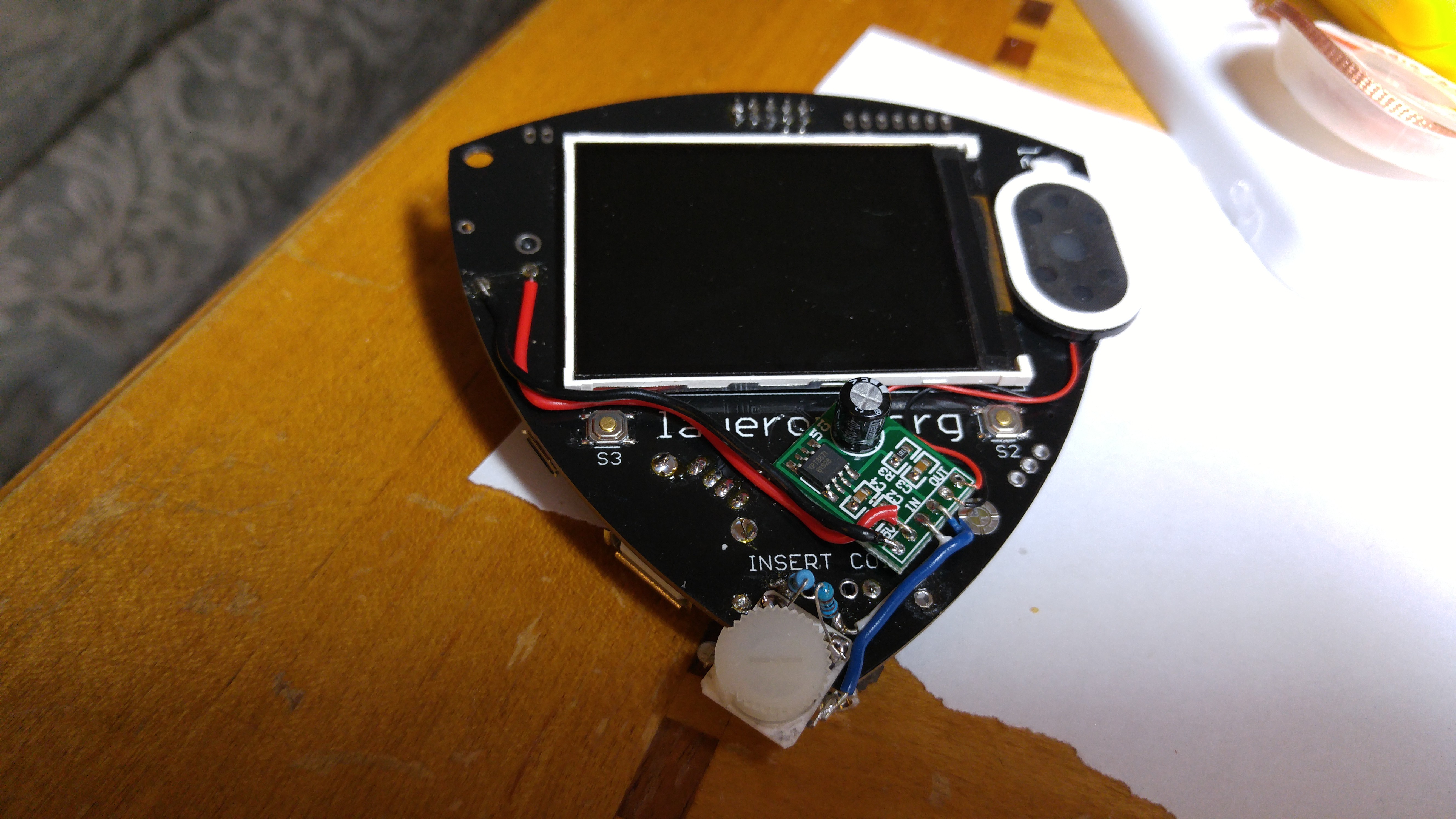
Now that I had all my parts chosen, and working on my desk with a slew of alligator clips, it was time to assemble it all together. In rough order:
- I removed the old voltage and signal test leads.
- Superglued the pot to the bottom edge, after bending the pins/supports in a useful way. I had originally tried hot glue here but it wasn't strong enough (or at least I was too impatient to let it fully cure).
- Soldered in the resistors between the signal lines and the pot.
- Hot glued the amp board on. While there's no real exposed connectors, the hot glue also forms a "pad"/air-gap ensuring nothing's shorting.
- I cut to length and soldered the wires between power, the pot, and the amp.
- Hot glued the speaker on, and cut and soldered it's wires.
Everything looked better than I expected.

Then I turned it on...
And nothing.

I tried:
- unsoldering power and signal lines
- checking for sloppy shorting soldering
- checked for burned out components
- charging the battery/trying a different one
- at best I can get only a quick flash of LED1
- tried USB power
- LED1 blinks repeatedly, but no screen
- I broke out the VOM and measure:
- With battery: 3V3 = 0V and 5V = ~0.5V
- With USB: 3V3 = 0V and 5V = ~4.8V
So I suspect something's wrong with the power regulator circuit.
At this point all the easy troubleshooting didn't resolve it.... not sure if/when I'll get back to this.
 Todd
Todd
Discussions
Become a Hackaday.io Member
Create an account to leave a comment. Already have an account? Log In.
@charliex
On VREG I measure:
* Input: 4.98V
* Output: 0.033V
* Adj/GND: 0V
* VOut: 0.037V so this does seem the issue
On MP3401:
* PGND: 0V
* Batt: 4.78V (battery not installed)
* VCC: 4.98V
* Out: 4.70V
* GND: 0V
Thanks!
Are you sure? yes | no
mmca, sorry, I just saw your comment now. Thanks. I'll check into that IC2 also - looks like it's a GH27G .... but again, I can't find a datasheet.
It physically looks ok. I just noticed there's no R13 populated.
Are you sure? yes | no
With USB, if you are seeing 4.8v on the 5V rail and no 3v3 at all... I wanna say its IC2, the SOT-223-3 part.
Will ask charliex to send one along with the MP3401.
Cheers.
Are you sure? yes | no
more than likely mp3401 has failed, pm me your shipping address and i'll send you a couple..
there is space on the board for an RC circuit for the audio output, they've got lines across the pads in hte pcb that need to be cut if you're going to drop in 0805 cap and resistor
also there is can software in the 032.la/svn repo
actually mmca said read the post, and i see you have 5v with usb and no 3.3v so check the input/output of the VREG, see if it's shorted and if 5v is going into it, i have not seen that failure more before
cheers
Are you sure? yes | no
Thanks Charliex. I did mention the RC circuit somewhere in my updates - I think you told me about it at the conference.
I'll look a bit closer at the MP3401. Did you have any luck finding a datasheet for it? I can only find sample circuits.
By "VREG" you mean the MP3401, right?
I have trying the CAN on my to-do list. Oh wow, SVN..... haven't seen that in a while ;)
Are you sure? yes | no
The 3.3V VREG is a different part, its the small 3 pin with tab part. The mp3401 is likely ok if you're reading 5V, since its making it.
yeah we've had that SVN server for years, and since there is usually only me working on it, it doesn't need the complexity of git or HG, but we have a github too
https://www.diodes.com/assets/Datasheets/AZ1117E.pdf is fine
i will post an english version of the MP3401 datasheet i made too.
Are you sure? yes | no