 artist_edge
We are servicing the tubes in preparation for this weekend's show. It's a good time to take some pictures of the tube internals.
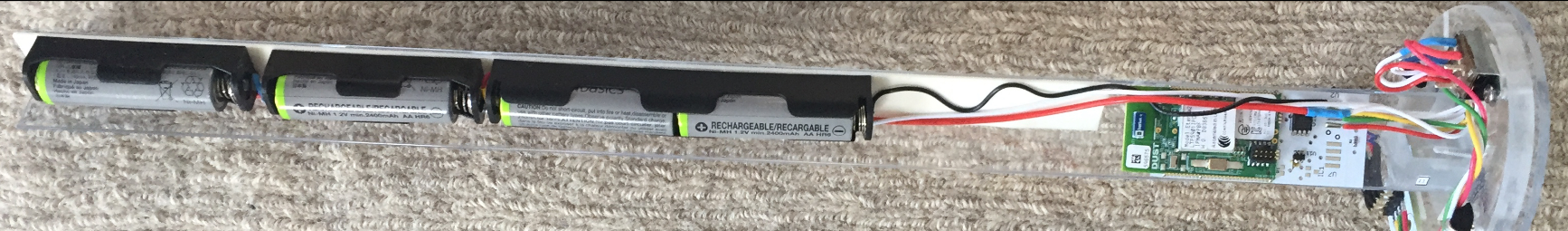
When you first pull out the central portion of the electronics (see directions for assembly instructions), You can see the battery section which is shown without the stabilizing cover, LED strips along length, and then end cap with the wireless module and microcontroller.
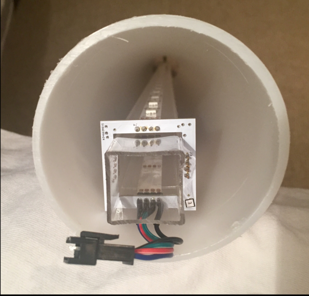
When seated inside the tube without the main board, the placement of the LEDs is clear. The Connector provides the bus connection to light up whole tube.
Here is a close up of the wireless module and how it is affixed to the central tube. There is some room for improving robustness but live and learn.

Discussions
Become a Hackaday.io Member
Create an account to leave a comment. Already have an account? Log In.