-
Follow me - part 4
09/09/2018 at 07:58 • 3 commentsIn the last attempt to make my robot follow me, I used a radio frequency of 433MHz with a small bandwidth of 90kHz. The major problem with this approach were reflections resulting in multipath interference. A technology immune against this issue is ultra-wideband (UWB), which is using a large bandwidth with more then 500MHz. The DWM1000 Module by Decawave is one implementation of UWB, quote:
"DWM1000 is an IEEE802.15.4-2011 UWB compliant wireless transceiver module based on DecaWave's DW1000 IC. DWM1000 enables the location of objects in real time location systems (RTLS) to a precision of 10 cm indoors, high data rate communications, up to 6.8 Mb/s, and has excellent communications range of up to 300 m thanks to coherent receiver techniques."
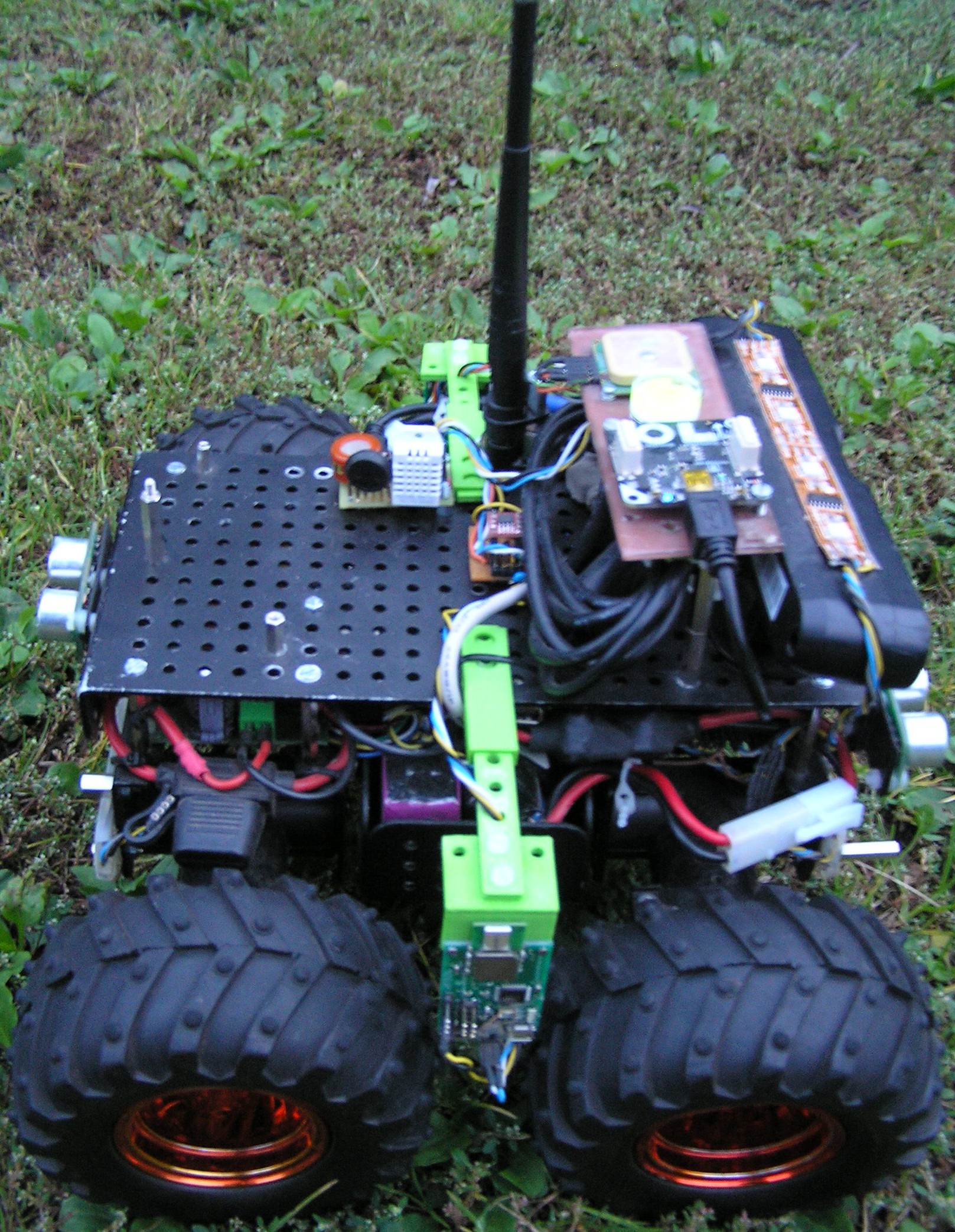
Originally designed for 2d/3d localization, the DWM1000 modules basically enable the measuring of the distance between a "tag" and an "anchor". To test the DWM1000 I bought three Localino v1.3 boards. One board includes a DWM1000 and an AVR Atmega328 where I installed an open source dw1000 library on. Two DWM1000 are mounted on my Wild Thumper robot, one on each side between the front and the aft wheel about 29cm apart.
![]()
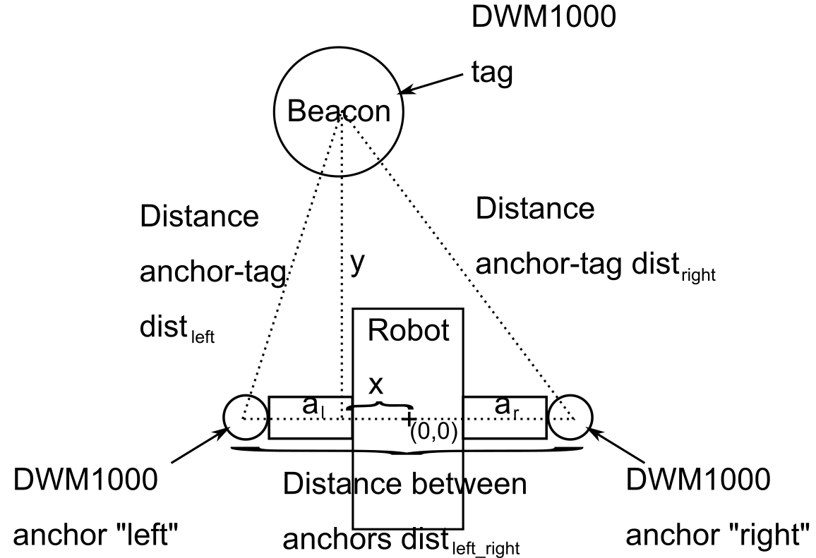
Both DWM1000 on the robot are configured as anchors. The third DWM1000 is configured as a tag and is the beacon that is to be followed:
![]()
Given the two distances dist_left, dist_right from both anchors to the tag and the distance between both anchors dist_left_right we get two right-angled triangles that share a side. With them the beacon position (x, y) from the center of the robot can be calculated using the Pythagorean theorem:
There are two solutions for these equations, one in front of the robot, one behind. Since the beacon is initially set up to be in front of the robot and is expected to stay there, only this one solution is taken. The calculated relative position of the beacon is then smoothed with a simple Kalman filter [1]. The prediction of the Kalman filter assumes a stationary object and is only adjusted when the robot itself moves. The prediction is corrected by the calculated x & y values from the equations above. The working code can be seen in the following video where the Wild Thumper robot follows a DWM1000 beacon which is mounted on a R/C car.
[1] The simple Kalman filter is based on the Matlab code in Xilinx Xcell Journal Issue 53, p. 74.
-
Light demo
08/12/2018 at 07:11 • 0 commentsA video for showing the led stripes:
Music:
-
Follow me - part 3
06/18/2018 at 10:55 • 0 commentsSince using a beam antenna wasn't as accurate as I hoped for direction finding (see previous log) I was looking for other alternatives, so I tried using the phase difference between two antennas, sometimes named tdoa. This method basically uses the doppler effect, but instead of rotating the antenna physically, the antenna is rotated virtually, by switching between one or more antennas. The idea is
- when one antenna is closer to the transmitter, there is an audible glitch in the signal
- when the transmitter is equidistant to the antennas, there is no change in the signal
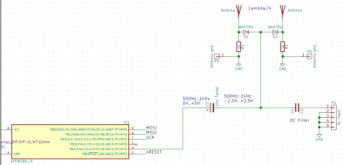
My phase difference receiver is using two antennas. Switching between two Lambda/2 antennas is done using RF Pin Diodes:
![]()
The diodes are driven with a PWM from an AVR Attiny. Using a capacitor the amplitude of the PWM is shifted to -2,5/+2.5V. The HF is connected to an rtl sdr, decoding is done with GNU Radio. The whole setup looks like this:
![]()
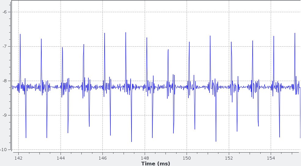
The transmitter has to be FM, the closest thing to that in my inventory was an RFM12 (433MHz), which does Frequency Shift Keying (FSK). I programmed the RFM12 to send a few zeroes so I can easily identify the signal. The result looks like this when the left antenna is closer:
![]()
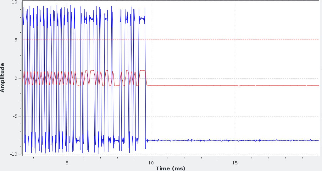
As one can see I use a PWM with a ratio of 30% : 70% to distinguish between both phases. When the right antenna is closer the spikes are inverted. When both antennas are equidistant distance from the transmitter the signal is not disturbed:
![]()
So the setup basically works, the robot can distinguish if the transmitter is closer to the left, closer to the right or equidistant to both antennas. But there are still a lot of problems, mostly from reflections which do make the robot drive to the wrong direction...
-
Updating the AVRs over I2C
01/19/2018 at 07:12 • 0 commentsThe wild thumper has an AVR Atmega32 and an Atmega328 microcontroller. Normally to flash a new firmware onto them I have to open the upper panel and attach my ISP. To workaround that I developed an I2C bootloader. After setting the fuse bits "Boot Reset vector Enabled" and "Boot flash section size"=1024 words the bootloader is programmed into the AVR.
On start the bootloader checks if the first byte in the flash is 0xff. If it is 0xff it assumes that the memory is erased and there is no valid program. Else it starts the main program by jumping to address 0x00. There is also the option to force the bootloader to run by writing the magic number 123 into the first address of the eeprom. When the bootloader runs it accepts commands from I2C (defaults to address 0x50/0x28). Commands include
- read memory
- write memory
- erase memory
- erase all
- and jump to address
I also wrote the corresponding client program which runs on the Linux computer. With this python script programming an AVR becomes to
./bootloader.py 0x52 main.hex -jFirst argument is the target address 0x52 (0x29), second argument is the program file to flash, -j tells the bootloader to start (jump to) program after flashing.
From now on I can update the firmware of all microcontrollers in the field without taking everything apart or attaching an extra programmer.
-
Follow me - part 2
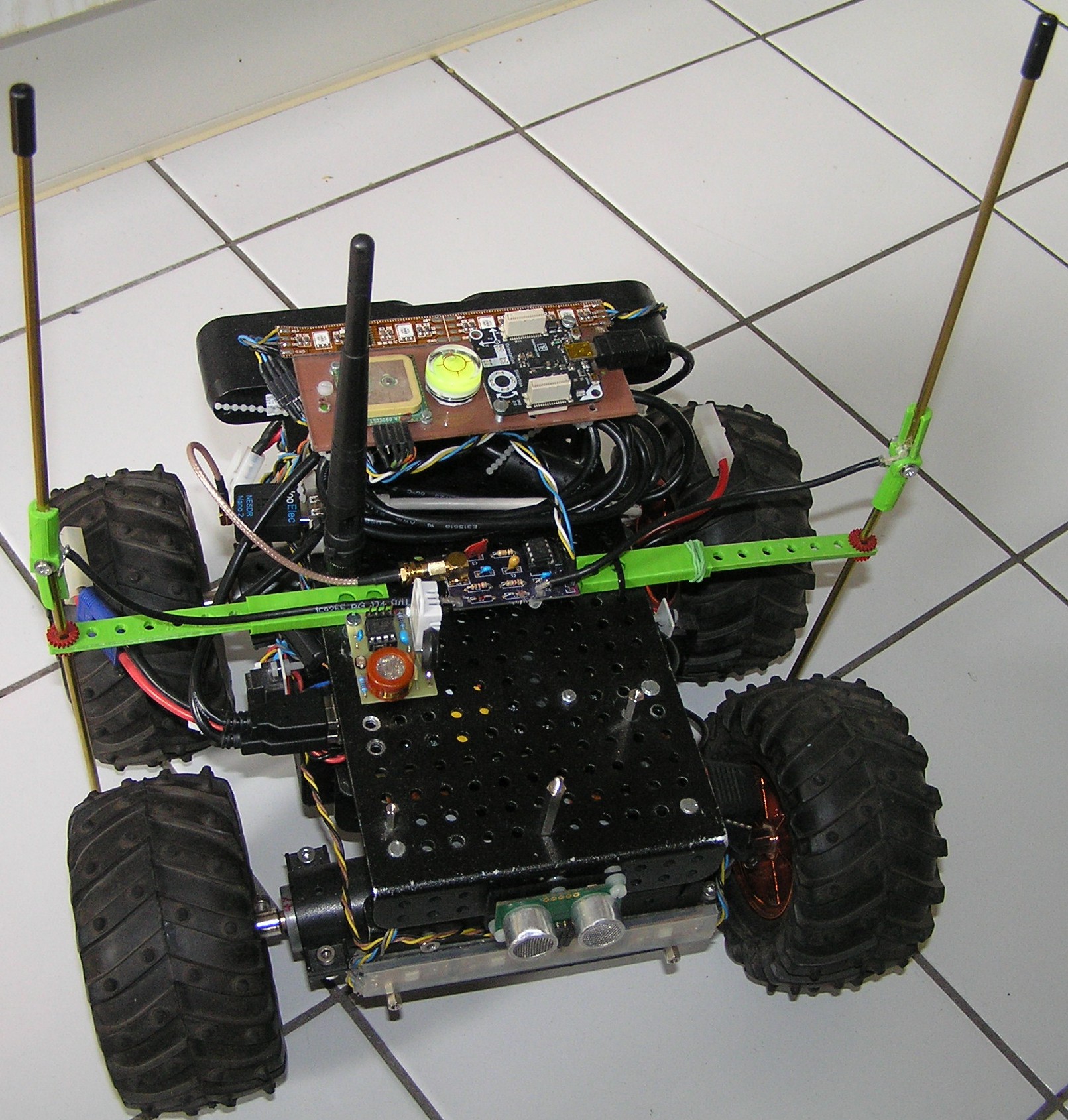
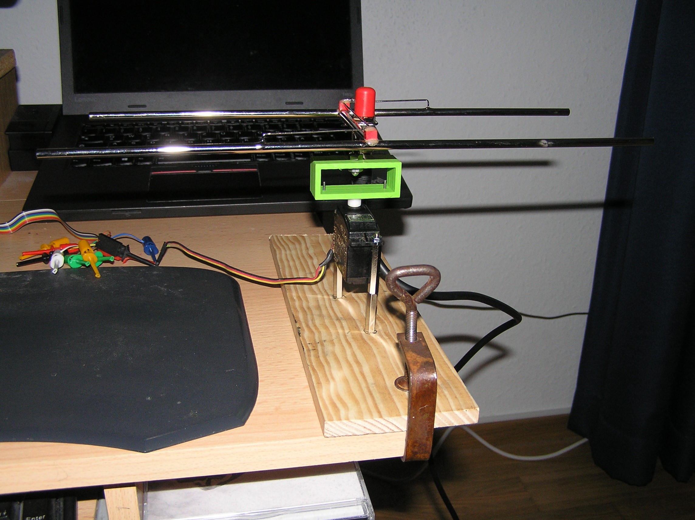
01/14/2018 at 09:46 • 0 commentsFInally got a HB9CV antenna, a BNC cable and a corresponding adapter to my RTL-SDR. I've put the antenna onto a servo and 3d printed an adapter, the whole setup looks like this:
![]()
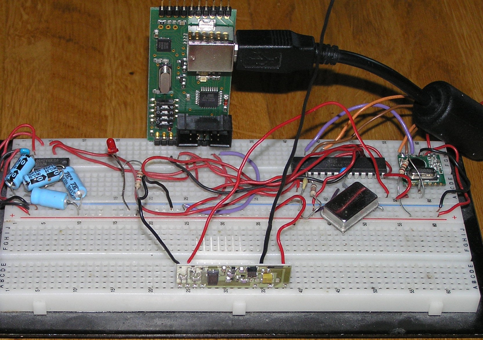
The beacon was quickly wired on a breadboard. The antenna does not have the correct length, but this was enough to receive a signal in a first test:
![]()
On the software side the beacon simply transmits "MO" in Morse code every 5s with currently 50ms for a dit and 150ms for a dah. I have to speed it up later. The first reception was done with multimon-ng. Minimum frequency of the transmitter is 433.82MHz, maximum is 434.02MHz, so I used the center frequency of 433.92MHz with a bandwidth of 200kHz. Gain was set to maximum and everything piped to multimon-ng:
rtl_fm -g 19 -f 433.92e6 -M am -s 200e3 -r 22050 - | multimon-ng -a MORSE_CW -t raw /dev/stdinAfter verifying that multimon-ng prints "MO" every 5s I wrote a small python script to decode the same output of rtl_fm. The data is sampled 45 times a second as short int:
SAMPLING_RATE=22050/45

frames = sys.stdin.read(SAMPLING_RATE*2) # Two bytes per value
data = np.array(struct.unpack("<%dh" % (len(frames)/2), frames))
and then the average is used to detect if this is a high or low level:
avg = np.average(data)
cur_level = avg > HIGH_THRES
With help of the Internet decoding the morse code was very. In the end every time I detected a "MO" I printed the average high level on the terminal.
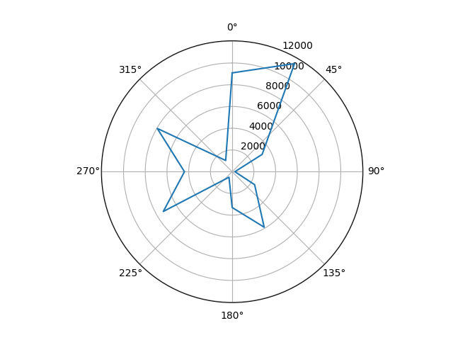
Using the average level I placed the beacon every 30° around the antenna with a distance of 1.5m to a get a radiation pattern of the antenna. My setup was not very accurate but it does give a first idea:
![]()
As one can see the maximum is not quite in front of the antenna, it does squint about 30°. But the decrease of values to 0° and 60° degree is clearly visible. The exact values in this area need more investigation.
-
Follow me - part 1
12/31/2017 at 09:25 • 0 commentsThe goal for 2018: Getting my robot to follow me. How can this be done? I checked a few options for this:
- Visually e.g. with OpenCVs Find-Object or OpenCVs camshift. However after playing with them I haven't found them robust enough. Maybe my camera or illumination could have been better?
- Ultrasonic as implemented by e.g. Robo-Dog. Seems to work good, but with limited range (few meters?) and you have to point the beacon towards the robot, that is not what I plan.
- Radio: The ham radio people have a game called "Amateur radio direction finding" (also known as fox hunting) where the hams are trying to locate a small beacon by using a direction finding receiver. There is a small howto on a cheap self made Transmitter & Receiver "Foxy" available (german) that should provide a good starting point. However I plan do use a AVR with a 434 mhz ook transmitter as beacon and my old RTL-SDR as receiver. Antenna will probably be a HB9CV. On ISM 433MHz the reception antenna will probably end up as big as my robot, so moving to a higher frequency (868MHz to 2.4GHz) might be obvious.
-
GPS test
12/16/2017 at 17:59 • 0 commentsDoing a GPS test by automatically driving a square with four GPS waypoints. The front camera is shown on the lower left, the rviz map video is shown on the upper left.
Music:
-
Rework
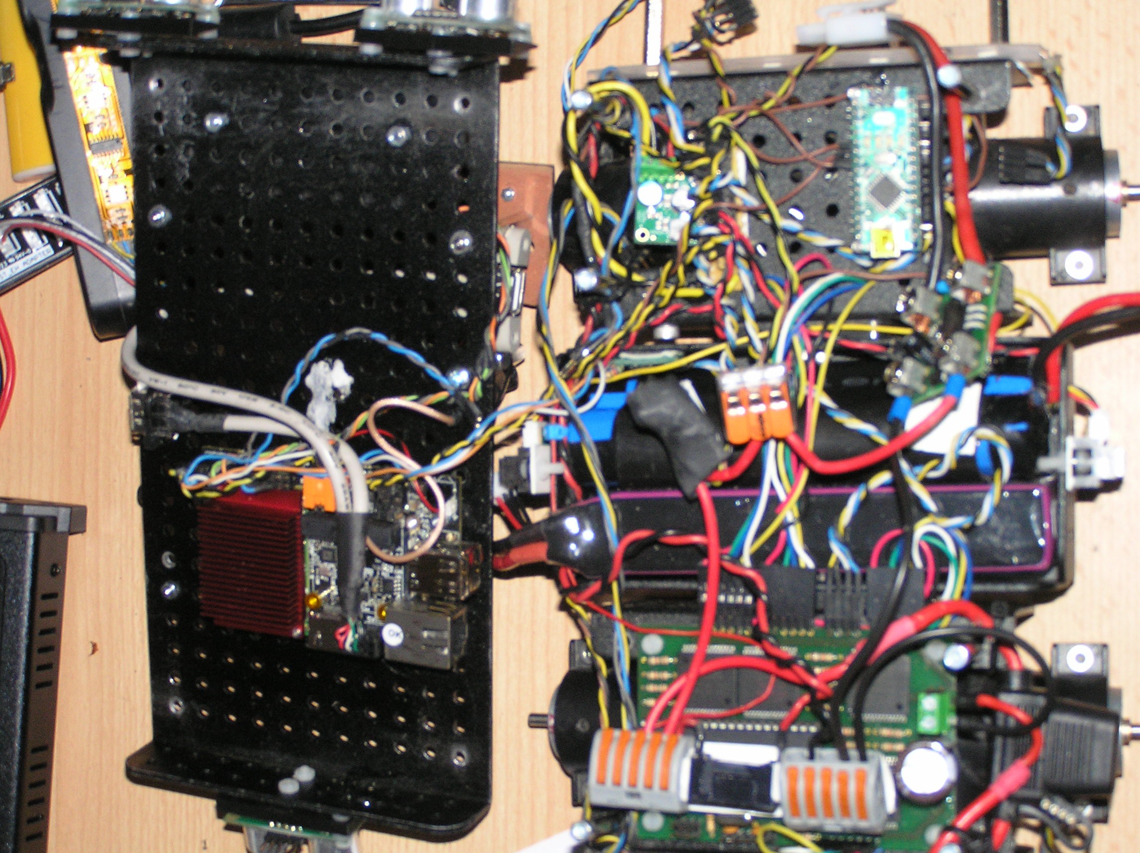
12/09/2017 at 19:57 • 0 commentsCurrently doing some rework and moving the single-board computer from the top to the interior, thought I share a picture from the inside:
![]()
-
Sonar sensor (here SRF05) tuning
07/09/2017 at 08:31 • 0 commentsROS supports sonar and infrared sensors with the sensor_msgs/Range Message. Using it is pretty straightforward, but there are two values that I have spend quite some time on tuning: field_of_view and max_range.
1. max_range:
The SRF05 has a maximum range of about four meter. But that is not what I have set as max_range value because of the high field of view of this sensor (see below) with a maximum of about 55°. That means in an area of four meter and 55° a table leg is enough to mark the full area as occupied. To avoid this situation I set the max range value to only 0.5 meter.
2. field_of_view:
The field of view is not constant. For the details hobbizine has a good article which I highly recommend to read, quote:
"The beam width (or beam angle) of ultrasonic range finders is typically described as being a cone of a certain angle (...) The conclusion of this logic would be that the detection zone extends from the sensor in an even, steadily expanding arc until it reaches the 4 meter limit of the SRF05 range. In reality the detection zone expands at about 55° for the first meter and then the rate of expansion starts to decay. At about 2 meters distance from the sensor the angle of the detection zone is closer to 40° with the zone reaching a maximum width of about 80-100 centimeters. From this point the detection zone will begin to narrow, ultimately reaching zero when the distance from the sensor is a little more than 4 meters."
I currently use 30° for the 0.5m max range
-
Rollover protection
07/02/2017 at 08:36 • 0 commentsRollover (vehicle overturns) is a problem for many vehicles with a relatively high center of mass. I have observed the following rollover scenarios for my Wild Thumper:
- When driving downhill
- When executing a fast forward/backward direction change
The obvious counter measure to avoid these dangerous conditions is to fully reverse speed when detected. The detection can be done with the IMU. So I added a listener for the IMU message and read the pitch angle from it:
- If the pitch is higher then 45° (the robot standing on the front wheels) the rollover protection will drive forward with maximum speed until the situation is resolved.
- If the pitch is lower then 45° (the robot standing on the back wheels) the rollover protection will drive backward with maximum speed.
No obstacles checks done. Lets hope that this will prevent the wild thumper from overturning ever again..
Wild Thumper based ROS robot
My ROS (Robot Operating System) indoor & outdoor robot