-
Razor IMU vs Tinkerforge IMU Brick 2.0: Magnetic interference
06/25/2017 at 10:15 • 1 commentI've used the Razor IMU for two years to correct the odometry from my 4wd base. Problem is when driving close to e.g. the dishwasher because of its magnetic field my robot always thinks that it is driving a curve while in reality it is driving straightforward.
I recently came across a demo video of the Tinkerforge IMU Brick 2.0 which advertises nearly immunity against magnetic interference. So I bought one and tested it.
At first the IMU Brick, with all the led it looks a bit like a Christmas tree. Fortunately they can be turned off. Software installation is complicated (requires to run a daemon). Also with 70mA the Brick draws a higher current at 5V then the Razor with 40mA.
I mounted it on the wild thumper together with the Razor IMU and was surprised that I got recently good values without any calibration, I calibrated it anyway.
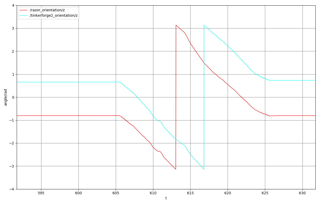
According to the datasheets the accuracy of both IMUs accelerometer, magnetometer and gyro is in the same magnitude. I started to plot the yaw (turn around z-axis) of both IMUs using rqt_plot. The result with a slow 360° turn has no surprises (Razor=red line, Brick=blue line):
![]()
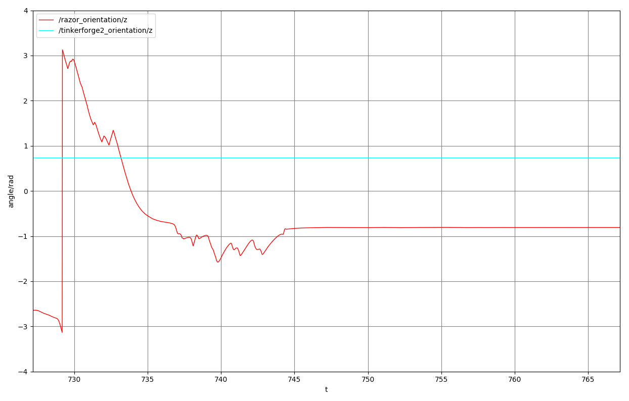
Next I brought a magnet close to both IMUs. Here is the surprise: Result is little to no visible change of the Bricks orientation:
![]() While the Razor IMU (red line) immediately reacted to the magnet the Brick (blue line) stayed nearly constant. Really awesome. That is why I'm using the Brick instead of the Razor IMU now.
While the Razor IMU (red line) immediately reacted to the magnet the Brick (blue line) stayed nearly constant. Really awesome. That is why I'm using the Brick instead of the Razor IMU now. -
2wd/4wd wheel odometry
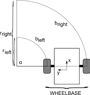
06/18/2017 at 09:07 • 0 commentsOdometry calculated from wheel encoders is used to estimate the position of a robot. Wikipedia has a good definition. Calculating the position of a robot with two main wheels (and a third caster wheel) from the revolutions of the wheels is pretty easy using basic math. With the robot in the following image we want to calculate the new position (x,y) and angle alpha:
![]()
We know the distance both wheels traveled which is b_left and b_right. As we can see in the image both values are distances on an arc. To get an angle from them we can use the following formula for each wheel:
More specific for the left and right wheel:
But do we know the radius? No, but we do know the wheelbase (the gap between both wheels):
So now we have three formulas with three unknown variables (b_left, b_right and alpha). Using them we can rearrange them to
and we have our new angle. We can now use the trigonometric functions to calculate our position offset
With the average between the left and and right arc as radius:
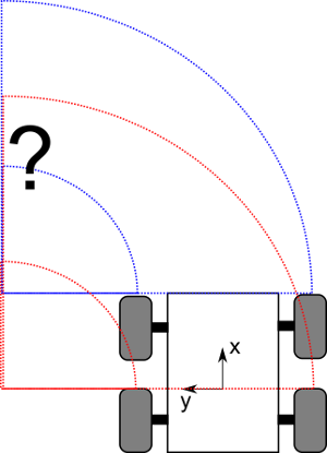
By now we have calculated the new position and angle of a two wheeled robot. But my wild thumper has four wheels. So to use the math from above I need to calculate with two virtual wheels instead, which are averaged from the front and aft wheel on each side. This works fine for translation, but not for rotation:
![]()
As one can see in the image when turning at least either the two front wheels, the two aft wheels or all wheels have to slip. Vehicles with chains have the same problem. This can also not be calibrated since it changes from surface to surface.
Translation errors have a constant effect on position. 1cm error will be 1cm after driving 1m or 5m. Errors in rotation have an increasing effect on position, only 1° error in angle results in a 2cm error after 1m and nearly 10cm after 5m.
This why an additional IMU is needed for correction of the complete 2d position (x,y, angle). IMU and wheel odometry are merged with a Kalman filter.
Wild Thumper based ROS robot
My ROS (Robot Operating System) indoor & outdoor robot
 While the Razor IMU (red line) immediately reacted to the magnet the Brick (blue line) stayed nearly constant. Really awesome. That is why I'm using the Brick instead of the Razor IMU now.