 Katherina Baranova
Now that we had all the components on the breadboard, we created the PCB layout in Eagle. The circuit schematics for the breadboard can be found in the link to the Dropbox folder below. The files are meant to be viewed in Eagle.
https://www.dropbox.com/sh/gi5cror21jhg31e/AABSWjdxS45kbxXIKgTCvaMYa
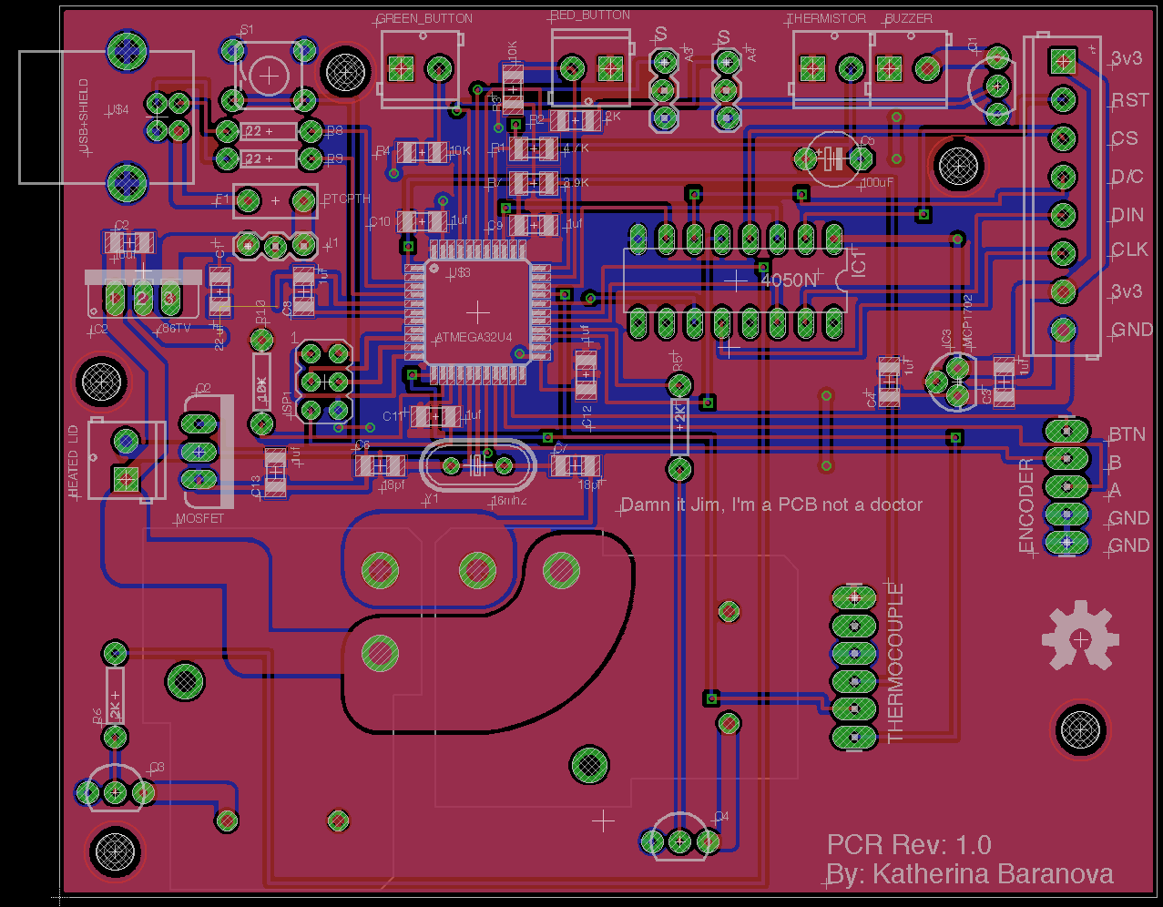
The schematic for the parts is shown below, as well as a screen shot of the PCB in Eagle.
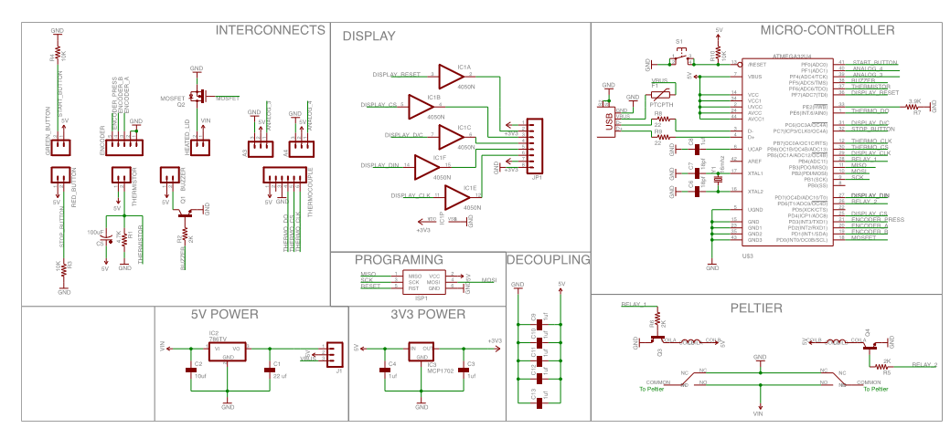
We added an encoder in the circuit which we intend to use to allow the user to set the temperature and scroll through options but have not written it into the code as of yet.
We then sent the circuit diagram to Itead studio:
http://imall.iteadstudio.com/open-pcb/pcb-prototyping.html
They sent us the finished board. We soldered on all the components, programmed the Atmega using our previous code and the Arduino IDE. These tutorials explain how to do it nicely:
http://arduino.cc/en/Tutorial/ArduinoToBreadboard
http://arduino.cc/en/Main/Standalone
We then connected everything to the PCR and we now have a working prototype. The next step will be to design and build a case. We also intend to make an interactive screen with options for temperatures and holding times, as well as an option for saving frequently used programs. We intend to improve this project as time goes on so we have a great thermal cycler!
Discussions
Become a Hackaday.io Member
Create an account to leave a comment. Already have an account? Log In.