Close
0%
0%

TimeBlock

A super-simple timekeeper

Similar projects worth following
TimeBlock is a simple timer with a 4 x 7-segment display run from an AVR and some associated circuitry. I designed and built it for a friend who's a private pilot. He asked for a very simple timer for keeping track of timing tasks while flying, without having multiple buttons or touchscreen as a distraction. After building it I found it useful in a few areas around the house where it's good to keep track of time (I was honestly pretty surprised at how useful this turned out to be).

Since this is the Internet, I can already hear the haters: "Why would anybody want this when everybody has a stopwatch on their phone already?" I thought the same thing initially, but after I built the first version for the guy who requested it, while testing I found it really useful in a few areas, particularly while cooking, outside grilling or while working out. Basically anytime where you might want an incrementing timer but your hands aren't free to unlock a phone.

The box's interface is as simple as possible: there's only one button. When the clock is off, press the button and the clock will start. If the button is pressed and released quickly while running, the clock will reset to zero and start over. If the button is pressed and held for 2 seconds, the box will measure the battery voltage and display it, then go to sleep when the button is released. If the box is left alone, it will count to 99:59 and then shut itself off. The AVR in deep sleep mode draws virtually no current, prolonging battery life. The 1000mAh lipo battery can be charged via a micro USB port on the side of the box.

The intensity of the display is adjustable by pressing and holding the button for > 4 seconds. The box will go into an 'intensity set' mode where intensity options from 1-9 are displayed. When the desired intensity is reached, releasing the button will reset the clock to zero and store the new intensity setting in onboard EEPROM.

A jumper allows the box to be powered directly from USB 5V rather than via the battery. If running the box this way, circuitry to measure battery voltage can be used to measure some external DC voltage, giving the option to make this a simple, USB-powered voltmeter. The box can be put in 'voltmeter mode' by setting a 2nd jumper on board. By default, the maximum voltage that can be read is ~4.5V, as the voltage reading was intended for a battery voltage with a max charge of ~4.2V. It is very simple to increase the voltage range (at the expense of resolution) with a few modifications to hardware/firmware as outlined in the manual.

LED_displayV5.sch

sch - 912.14 kB - 07/22/2017 at 20:04

Download

LED_displayV5.brd

brd - 146.51 kB - 07/22/2017 at 20:04

Download

Time Block.docx

A manual for the Time Block that covers operation, hardware functionality and firmware flow.

document - 1.35 MB - 07/22/2017 at 19:41

Download

topAndBottom_clock.stl

stl file for the box with a deeper bottom to account for a liPo battery

Standard Tesselated Geometry - 245.88 kB - 06/30/2017 at 23:41

Download

topAndBottom_voltmeter.stl

stl file for the box with a shallow bottom when using the display board as an externally powered box (no battery).

Standard Tesselated Geometry - 246.66 kB - 06/30/2017 at 23:41

Download

View all 6 files

  • Code is on GitHub!

    roger_archibald07/22/2017 at 19:54 0 comments

    Code was just uploaded to GitHub for this thin, linked below:

    GitHub link to TimeBlock code

  • Name-Change

    roger_archibald07/22/2017 at 19:50 0 comments

    There was already a project on here very similarly named to ClockBox and a friend who I gifted one of these to suggested I call it TimeBlock, due to its block shape and its potential usage in time-blocking, a strategy to organize time.  

  • video posted

    roger_archibald07/01/2017 at 17:35 0 comments

    I've edited the project details to include a video of this thing in action with a bit more details on the operation....Just doing a bit more firmware tidying so it's more readable and I'll post that as well.

  • schematics uploaded

    roger_archibald06/29/2017 at 12:12 0 comments

    Now that I've verified the latest revision is working, I uploaded the Eagle files as well as a pdf of the schematic. Firmware to come shortly, I just want to go through my code and clean things up a bit before I put it out there, so it's more readable.

  • Everything's looking good...except for the artwork

    roger_archibald06/26/2017 at 16:29 0 comments

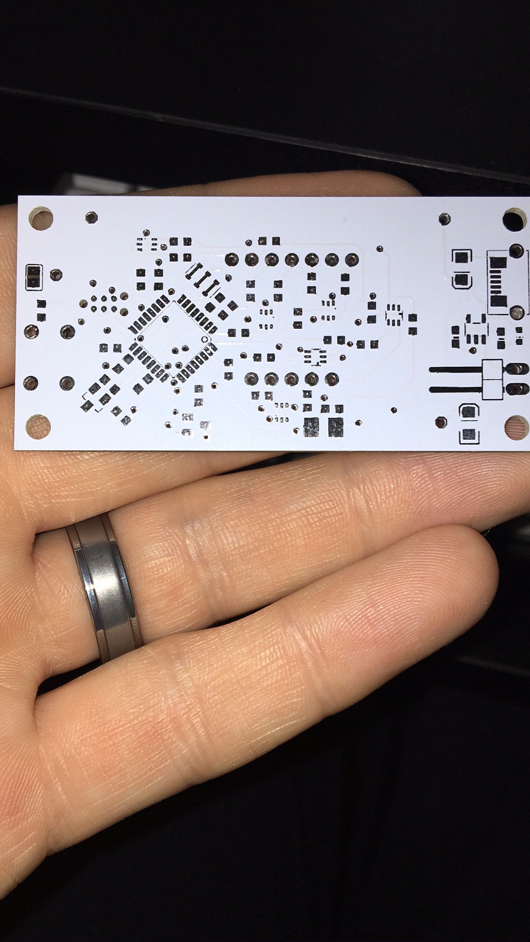
    The latest PCB's arrived from China while I was sitting in a hotel room in China, but after getting back state-side I got a couple boards stuffed and successfully tested. Things are looking great with the exception of my messing up the Gerber generation and these PCB's not having any reference designators. I'm hoping to get a chance to put together a video demonstrating the use and various modes of operation in the next couple of days...If I get these on Tindie, botched boards will be going cheap!

  • Latest Boards Delivered

    roger_archibald06/20/2017 at 22:20 0 comments

    The latest (hopefully final???) revision of PCB's just landed at my house. I'm out of town for a few days but hope to get these stuffed, tested and then finish up the documentation when I return.

View all 6 project logs

Enjoy this project?

Share

Discussions

Similar Projects

Does this project spark your interest?

Become a member to follow this project and never miss any updates