Close
0%
0%

Third Eye for The Blind

An innovative wearable technology for visually impaired.

Similar projects worth following
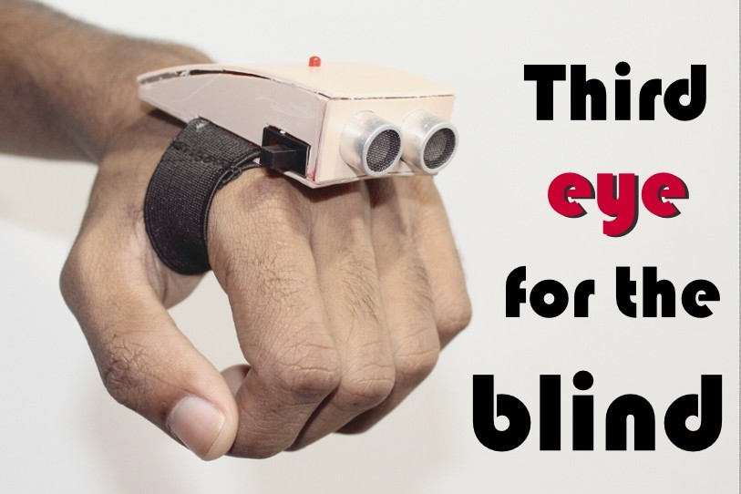
Third eye for blinds is an innovation which helps the blinds people to navigate with speed and confidence by detecting the nearby obstacles using the help of ultrasonic waves and notify them with buzzer sound or vibration. They only need to wear this device as a band or cloth.

According to WHO 39 million peoples are estimated as blinds worldwide. They are suffering a lot of harder ship in there daily life.The affected ones have been using the traditional white cane for many years which although being effective, still has a lot of disadvantages. Another way is, having a pet animal such as a dog, but it is really expensive. So the aim of the project is to develop a cheap and more efficient way to help visually impaired to navigate with greater comfort, speed and confidence.

Watch the video of it's working.

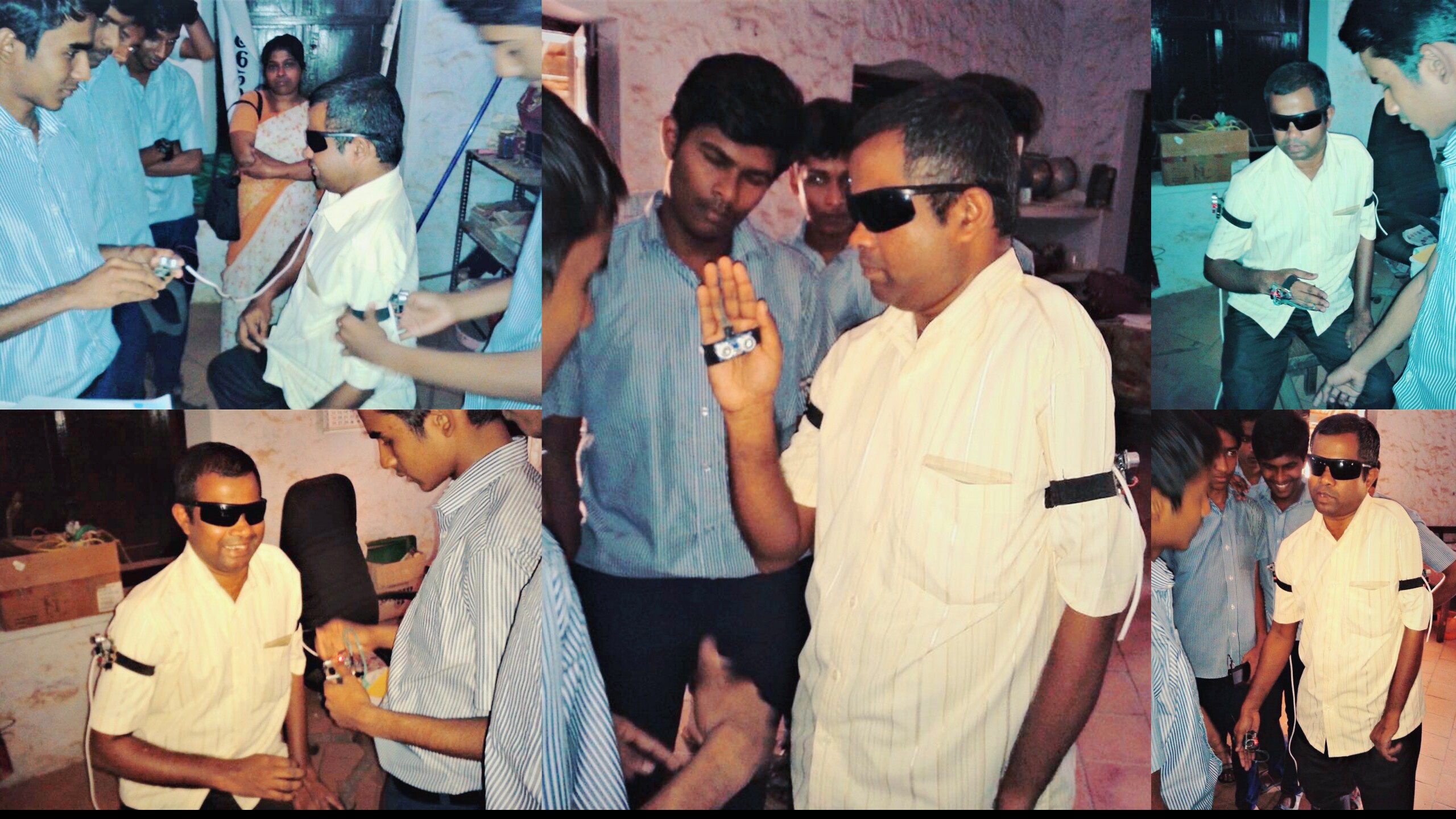
Watch the video that came in a news channel (Malayalam language)


Novelty of the project
This is the first wearable technology for blinds which resolves all the problems of existing technologies. Now a days there are so many instruments and smart devices for visually impaired peoples for navigation but most of them have certain problems for carrying and the major drawbacks is those need a lot of training to use. The one of the main peculiarity of this innovation is, it is affordable for everyone, the total cost being less than $25 (~1500INR). There are no such devices available in the market that can be worn like a cloth and having such a low cost and simplicity. When used on a large scale, with improvements in the prototype, it will drastically benefit the community.


Existing Systems
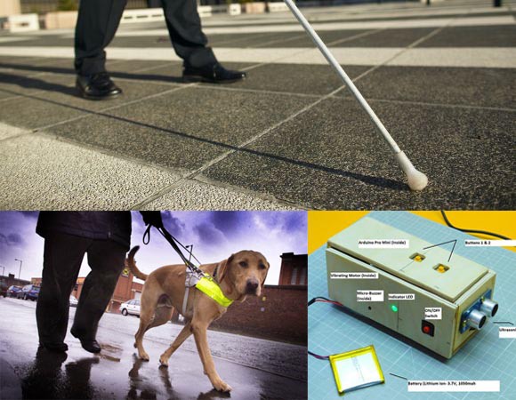
1.White cane

2.Pet dog

3.Smart devices (eg : Vision a torch for blinds)

Problem of the Existing Systems:
* White cane - May easily crack/break,The stick may get stuck at pavement cracks of different objects.

* Pet dog - Huge cost. (~$42,000 / 280000Rs )

* Common Disadvantages (Including the the smart devices) Cannot be carried easily, needs a lot of training to use…

The features of Third eye for blinds:

By wearing this device they can fully avoid the use of white cane and such other devices. This device will help the blind to navigate without holding a stick which is a bit annoying for them. They can simply wear it as a band or cloth and it can function very accurately and they only need a very little training to use it.


Full Description of the Project
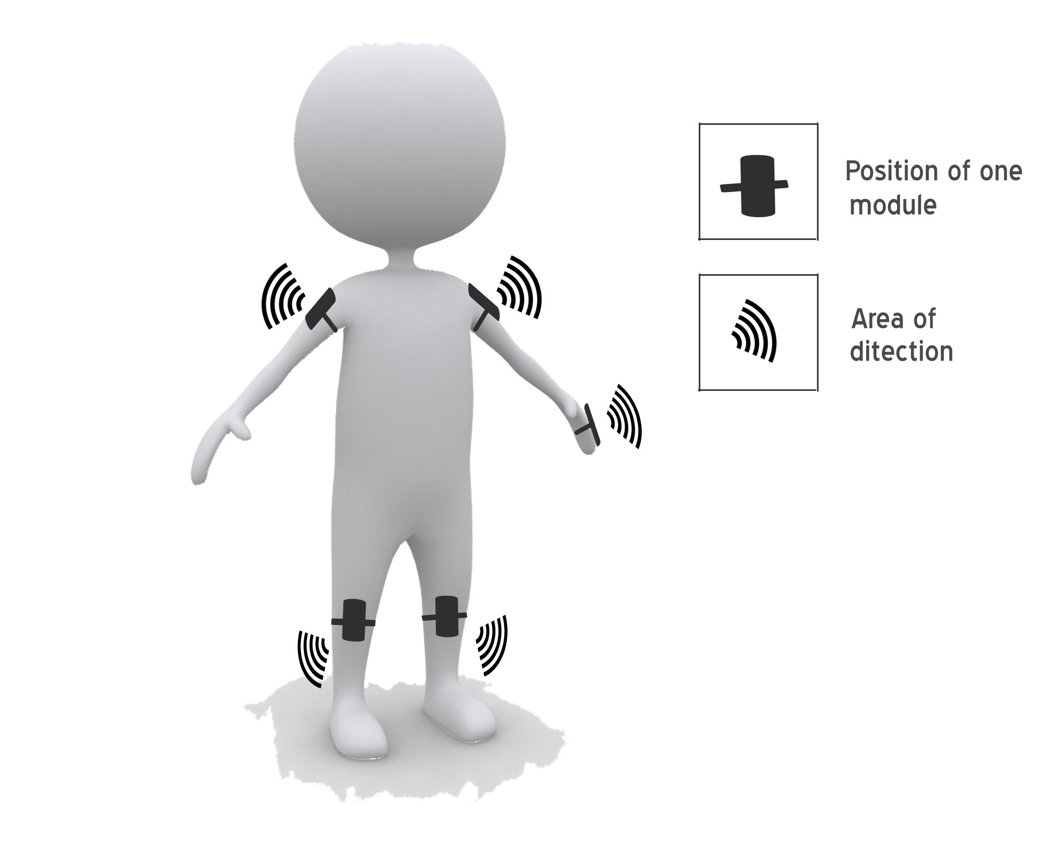
I have designed a special wearable device based on the arduino board which can be worn like a cloth for blinds. This device is equipped with five ultrasonic sensors, consisting of five modules which are connected to the different parts of the body. Among them, two for both shoulder, another two for both knees and one for the hand. Using the five ultrasonic sensors, blind can detect the objects in a five dimensional view around them and can easily travel anywhere. When the ultrasonic sensor detects obstacle the device will notify the user through vibrations and sound beeps. The intensity of vibration and rate of beeping increases with decrease in distance and this is a fully automated device.

Feature improvements

The entire project can be made in the form of jacket, so that the device doesn't need to be wear one by one. Use of specially designed boards instead of arduino and high quality ultrasonic sensors makes faster response which make the device capable of working in crowded.

Third_eye_for_blinds.ino

Code used in the arduino board.

ino - 1009.00 bytes - 06/17/2017 at 12:34

Download

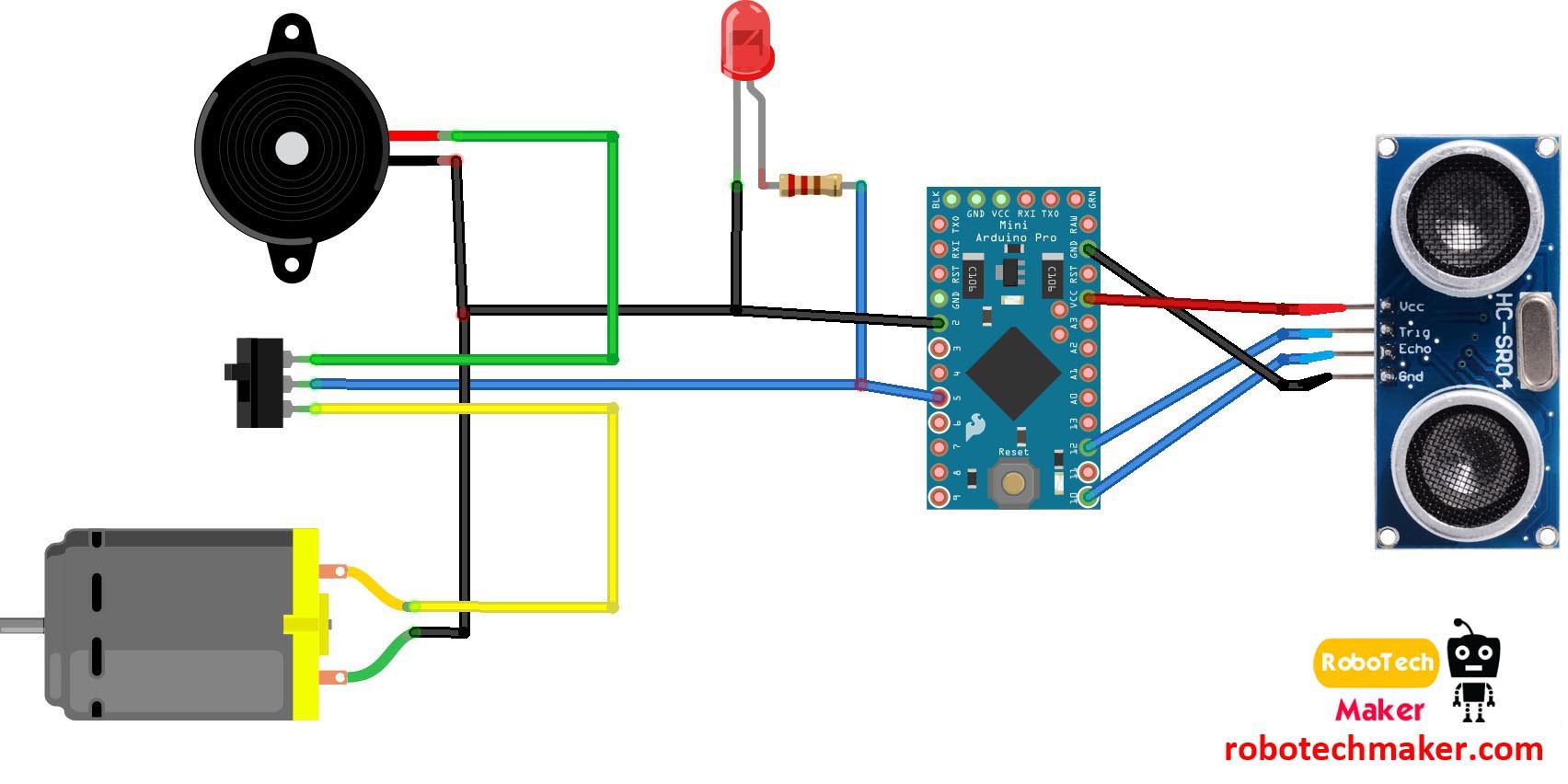
Circuit diagram.jpg

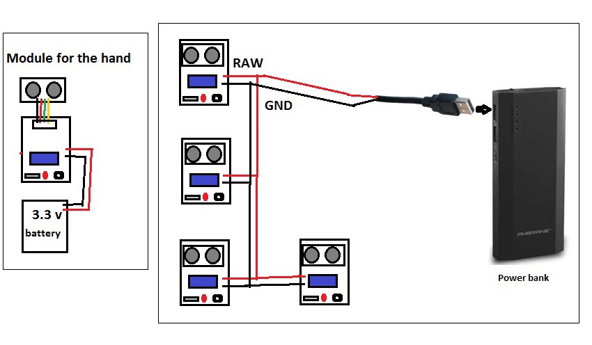
Circuit diagram of one module

JPEG Image - 132.41 kB - 06/17/2017 at 12:13

Preview

Connection diagram.jpg

Connection diagram of all 5 modules.

JPEG Image - 137.30 kB - 06/17/2017 at 12:13

Preview

  • 5 × Arduino pro mini
  • 5 × Ultrasonic sensor
  • 5 × Perfboard
  • 5 × Vibrating motor
  • 5 × Buzzers

View all 12 components

View all 2 project logs

  • 1
    Step 1

    Circuit Diagram - Descriptions.

    Wiring instruction.

    Ground of LED, buzzer and vibration motor to GND of arduino

    +ve of LED and middle leg of switch to Arduino pin 5

    +ve of Buzzer to first leg of switch

    +ve of Vibration motor to third leg of switch

    Ultrasonic sensor

    Ultrasonic sensor pin VCC - Arduino pin VCC

    Ultrasonic sensor pin GND - Arduino pin GND

    Ultrasonic sensor pin Trig - Arduino pin 12

    Ultrasonic sensor pin Echo - Arduino PIN 12

    The switch used here is for selecting the mode. ( buzzer or vibration mode.)


    Figure 2 - Powering the modules - Connect the 4 arduino pro mini to a USB male pin and connect to a power bank. For the module in the hand use a small lithium battery.

  • 2
    Step 2

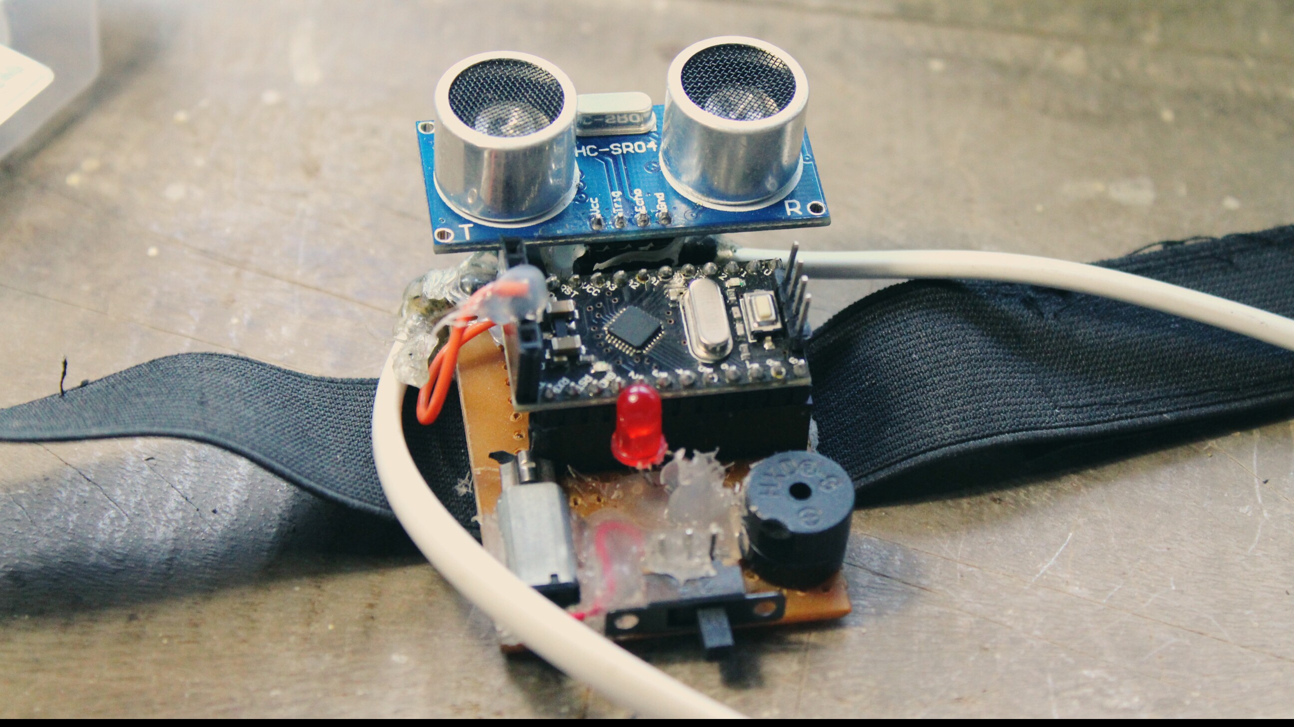
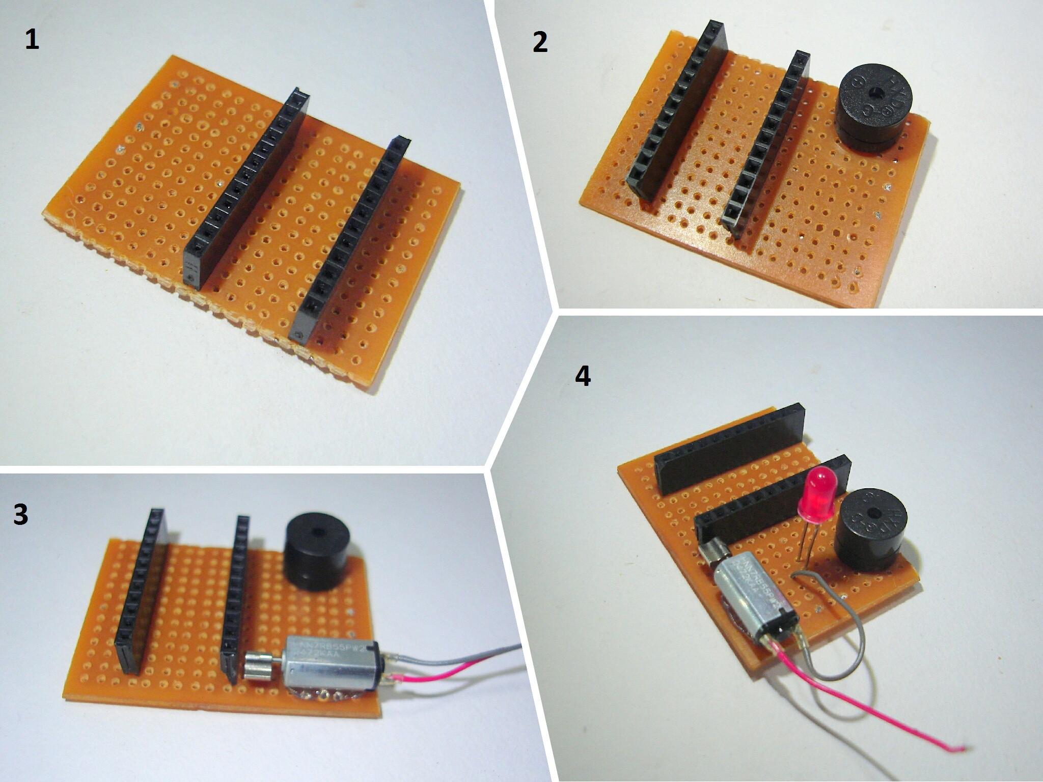
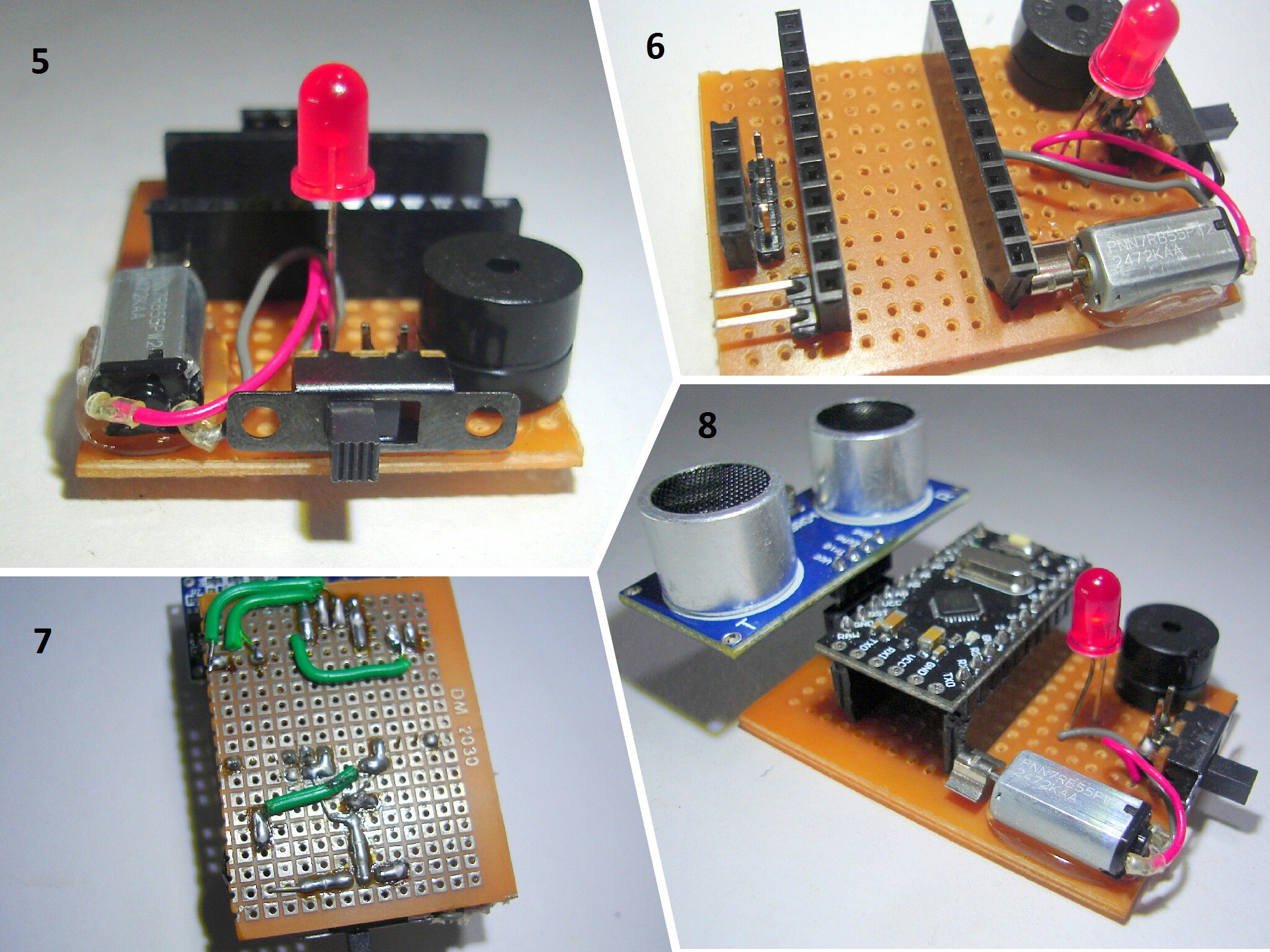
    Making the Modules

    1. First cut the pref board in 5 X 3 cm dimension and solder the female headers for the arduino to the board.
    2. Then solder the buzzer.
    3. Then connect the vibrating motor using the glue gun and solder wires to it.
    4. Then connect the LED.
    5. Then connect the switch.
    6. Then connect header pins for ultrasonic sensors and for battery input.
    7. Then solder everything as shown in the circuit diagram.
    8. Now connect the arduino and ultrasonic sensor to the board

    Also connect the elastic band to all the modules.

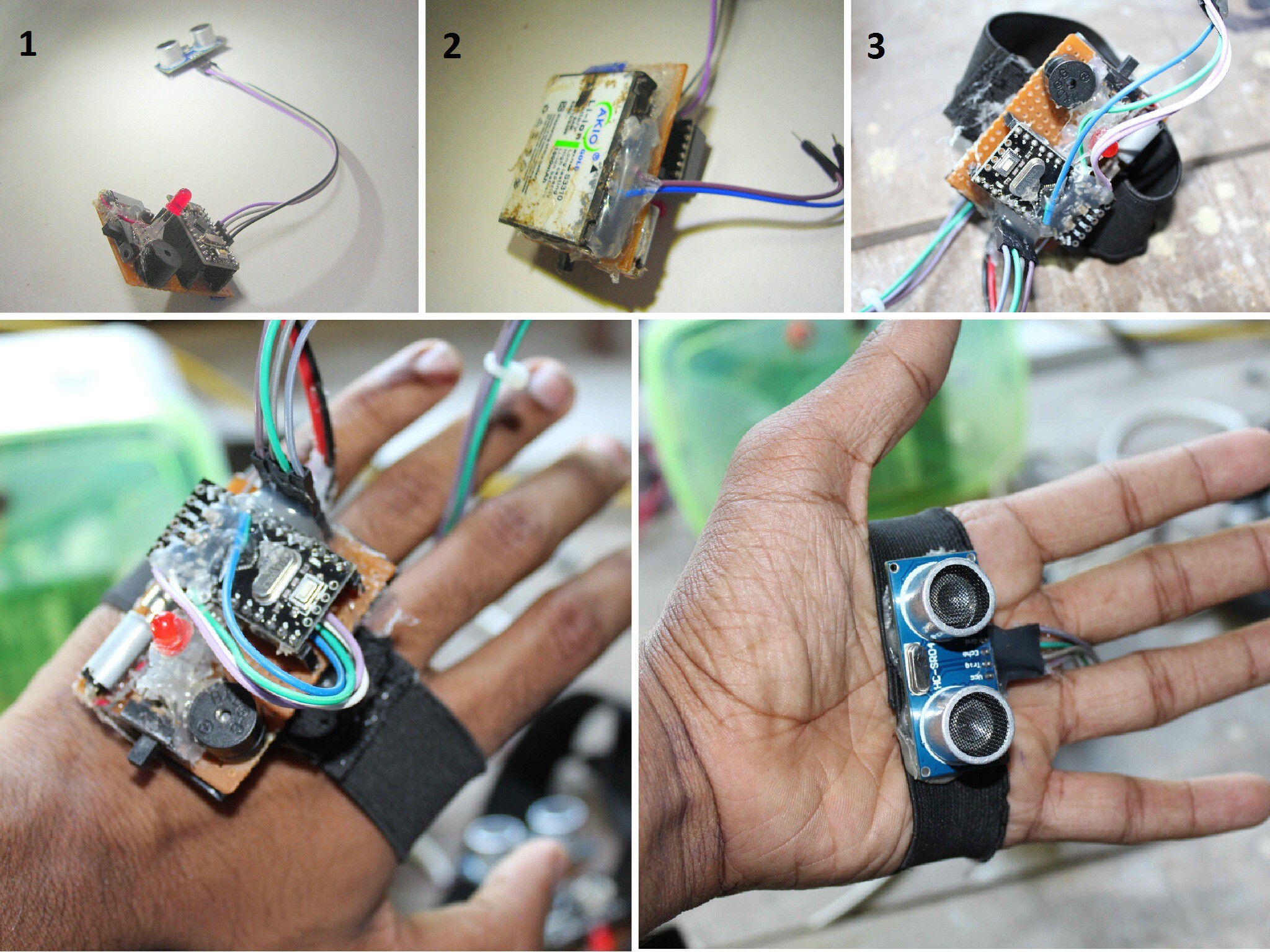
    3 more modules are to be made in the same way us described above, but for the one in the hand, there is a little difference. visit the next step before making that last module

  • 3
    Step 3

    Code + Making the Module for the Hand

    1. Connect the ultrasonic sensor to the board by using 4 jumper cables.
    2. Then connect a 3.7 volt mobile battery to this module.
    3. Then connect the elastic band as shown in the figure.

    At last upload the code to each arduino board and power the 4 other modules using a power bank.

    Code used in the arduino -

      //VISIT : www.robotechmaker.com
    
      const int pingTrigPin = 12; //Trigger connected to PIN 7   
      const int pingEchoPin = 10; //Echo connected yo PIN 8   
      int buz=5; //Buzzer to PIN 4   
      void setup() {   
      Serial.begin(9600);   
      pinMode(buz, OUTPUT);   
      }   
      void loop()   
      {   
      long duration, cm;   
      pinMode(pingTrigPin, OUTPUT);   
      digitalWrite(pingTrigPin, LOW);   
      delayMicroseconds(2);   
      digitalWrite(pingTrigPin, HIGH);   
      delayMicroseconds(5);   
      digitalWrite(pingTrigPin, LOW);   
      pinMode(pingEchoPin, INPUT);   
      duration = pulseIn(pingEchoPin, HIGH);   
      cm = microsecondsToCentimeters(duration);   
      if(cm<=50 && cm>0)   
      {   
      int d= map(cm, 1, 100, 20, 2000);   
      digitalWrite(buz, HIGH);   
      delay(100);   
      digitalWrite(buz, LOW);   
      delay(d);  
      }   
      Serial.print(cm);    
      Serial.print("cm");   
      Serial.println();   
      delay(100);   
      }   
      long microsecondsToCentimeters(long microseconds)   
      {   
      return microseconds / 29 / 2;   
      }   
       

    Thank you!

View all 3 instructions

Enjoy this project?

Share

Discussions

Radu Motisan wrote 07/16/2017 at 17:19 point

congrats, this is a simple device and so affordable, yet with considerable potential to help those in need.

  Are you sure? yes | no

lifenutritionsa wrote 12/21/2017 at 11:59 point

Hi, I am a blind person myself and is currently in the prossess of starting a project myself.  I would like to communicate with you if possable lifenutritionsa@gmail.com.  The biggest issue is steps

  Are you sure? yes | no

Similar Projects

Does this project spark your interest?

Become a member to follow this project and never miss any updates