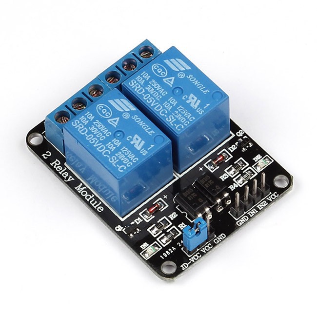
This is a standard 2 relays for Arduino, very cheap and easy to find online.

This module is made with some components inside, like optocoupler and diode.
The microcontroller is a low power supply device, without relay it can not control high power supply, like the power supply in the 3D printer.
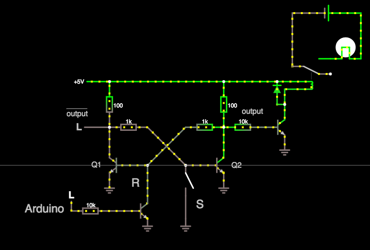
The basic function is schemed in this picture:
The rule of this component it's easy:
when the current pass through a coil - the component draw like a punch - the switch move, the C connection, from NC to NO. So, when the current not pass in a coil, the circuit return at NC.

Online simulator: http://tinyurl.com/yagvhscd
Why i added the transistor, resistor and diode on the output of the Flip-Flop?
These three components are integrated in the relay module. The resistor is put to put the transistor in the saturation region and the diode prevents the voltage spike when the inductor is discharged.
Now is the time to build the first prototype on the PCB board, according with the last circuit on the top.
 Dave
Dave
Discussions
Become a Hackaday.io Member
Create an account to leave a comment. Already have an account? Log In.