I figured now is the time to try to get the touchpad working. Some searching on the internet shows that touchpads normally have a PS/2 or a USB interface. So it must be doable.
Finding the pinout
Searching on the internet showed me that there is no standard. There was this, which helped me later on, because one of the pinouts here is close to mine (but mirrored). My measurements from the touchpad in the original laptop were as follows:
1: 5V - 2: around 1V - 3: GND - 4: 5V - 5: (resistance) - 6: GND*
My first guess was that 4 was a pulled up data line, and 5 a clock line that was idling. I think. Or I thought 2 was clock. I don't know anymore. Anyway, both 1 and 6 could be the power supply. To verify that guess without trying at the risk of blowing the thing up, I measured my way through the ribbon cables. Two ribbon cables are involved: motherboard (cable) switches (cable) touchpad. The first thing that struck me was that even though the connectors and the cables were the same, the pinout was completely different.
Only the pins 1-2-3-6 were connected to the touchpad, to pins 2-6-5-1*
GND was of course an easy one to find. The buttons were connected to the touch pad at pins 3 and 4. That left the V+ and the clk, data lines. Measuring the resistance led me to finding the V+: a resistance of 0 ohms rapidly going up, indicating a small decoupling capacitor being charged. The two 'open resistance' lines could both be CLK and DATA.
After measuring this, my guess was that it would be USB; that has a pull up on one of the lines. After the max of 4 tries (USB D+/D-, USB D-/D+, PS/2 CLK/DATA, PS/2 DATA/CLK) I got no response whatsoever. A night's sleep later and a better look: I didn't connect one of the wires correctly. Now I did, and my 4th updated try was working!
Found pinout & connected to a USB adapter
The final pinout, in USB colors is:
Red, Black, RightButton, LeftButton, Green, White for the TM278 itself (pins 1..6)
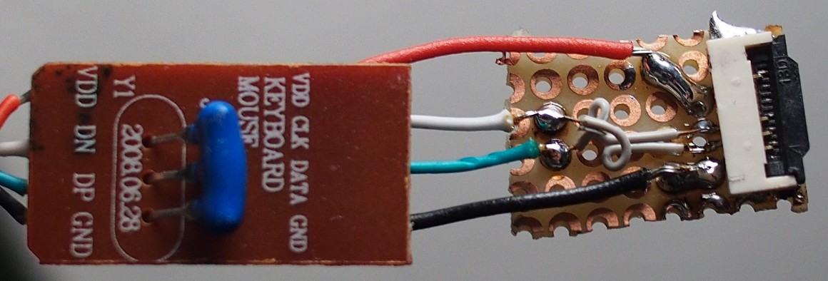
Red, NC, NC, Green, White, Black for the motherboard connector (see below for a clear image)
Opening up a PS/2 to USB adapter (keyboard + mouse) that was lying around showed a nice small PCB. Some careful soldering later (with one of the PCB pads split up so the two tiny wires could be connected) I got it working and robust enough to fit inside the laptop. I removed the two NC pins.

The CLK and DATA had to be mirrored which is done by the tiny wires.
Sadly, the 'mouse' is not detected when I plug it into the USB hub before plugging the hub into a computer. Perhaps I need some disconnect/reconnect simulation logic for this to automatically work.
* Please only trust the final pinouts. I did my best to write down my scribblings correctly, but may have made a mistake. Or: even don't trust the final pinouts. Measure yourself if you want to be sure. :)
Project renamed
I like "Scraptop" better. Sounds good, and describes what it is.
Discussions
Become a Hackaday.io Member
Create an account to leave a comment. Already have an account? Log In.
Thank you for the great writeup!
Are you sure? yes | no
Thanks for your comment. I hoped it would be of use/interest to someone. :) I'm so happy when I find something (almost) fit to my need which is otherwise out of reach to my skills (like driving an e-ink display, recently) that I did my best to document this quite thoroughly. As well as for possible future reference for myself, of course...
Are you sure? yes | no