 Rory Aronson
-
2014 Hackaday Prize, semifinals video
07/18/2015 at 16:57 • 0 commentsCheck out this video update of the newest FarmBot hardware and web application for our Hackaday prize Contest Entry!
-
Universal Tool Mount Testing
08/28/2014 at 21:17 • 0 commentsThis is a demonstration of the newest FarmBot Universal Tool Mounting System based on magnetic coupling of the tool to the tool mount.
-
FarmBot - Accelerated
08/28/2014 at 20:36 • 0 commentsOne of our project's software contributors, Tim Evers, just updated the Raspberry Pi and Arduino codebases for FarmBot to support acceleration! Before these updates, FarmBot performed very abrupt movements because the software would drive the motors from standing to full speed and back to standing in an instant; there was no smooth acceleration function built in.
Now, the motors are ramped up to full speed and back down over a period of time. This is especially important for FarmBot because the motors are relatively small (NEMA 17) for the size and mass of the FarmBot gantry system. Before the update, the stepper motors would occasionally "miss steps" meaning that the microcontroller told the motor to turn, but there was too much opposing torque and so it did not in fact move as expected. This creates a situation where the microcontroller thinks FarmBot is in one location, when it is actually somewhere else. Subsequent movements could cause wasted water, damage to the machine, or the destruction of the plants - all bad!
-
OpenFarm - The Database That Drives FarmBot
08/28/2014 at 20:10 • 0 commentsWe launched a Kickstarter campaign for OpenFarm, a free and open database for farming and gardening knowledge! OpenFarm came out of the need for FarmBot to access structured, detailed data for how to grow a plant in a specific environment with specific growing practices.
We found that this data did not yet exist and figured the best way to obtain it was with a website where anyone could contribute the data, much like Wikipedia. We then figured that if we were to build such a database, it should not be exclusive for FarmBot users, but accessible by anyone via an API, open licensing, and a dedicated frontend interface.
Check out the campaign and help fund this project!
//////////// From the Kickstarter Campaign:
Help us build the Wikipedia for farming and gardening!
The Problem
When searching for plant growing advice, it is common to run into the following situations:
- Advice is overly generic
- Advice is not structured, written, nor formatted well
- Advice is very specific, but not relevant to you or your garden
- There is no way to discuss or contribute new advice
The OpenFarm Solution
OpenFarm is a free and open database for farming and gardening knowledge. Similar to Wikipedia, the data is free for everyone to access and anyone can contribute content. Because people grow plants differently based on environmental conditions and growing practices, OpenFarm provides a framework for everyone to share their story, and for learners to find the best, most relevant content.
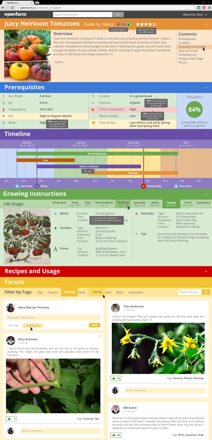
OpenFarm Growing Guides are structured stories for growing a specific plant with particular practices and environmental conditions. Below, is a mockup example of Nancy's Guide for growing Heirloom Tomatoes with organic practices, in a greenhouse. Below the image are descriptions for each of the sections of the guide.
![Click here for a larger view of the image!]() Click here for a larger view of the image!
Click here for a larger view of the image!See what the Growing Guides will look like on a smartphone here.
In the example above, the Overview serves to introduce the reader to the guide by providing a photo of the plant at its maturity and a personal note from Nancy. There is also a table of contents for quickly jumping to another section.
Next is the Prerequisites section. Nancy has specified what prerequisites are required for her Guide, and based on the reader's OpenFarm profile a "Compatibility Score" is created. In the example above we see that Nancy's guide is 84% compatible with the reader and their garden because most of the prerequisites have green backgrounds, indicating that they are satisfied. Others have yellow and red backgrounds, indicating that they are not fully satisfied. Mouse-over tooltips show why each prerequisite was satisfied or not.
Following the Prerequisites section is the Timeline, allowing the reader to quickly see if it is the right time of year for them to grow the plant. The timeline is based on the reader's local weather history, and the Growing Degree-Days that the plant is projected to experience in that location.
If Prerequisites are met and it is the right time to grow the plant, the reader reaches theGrowing Instructions which are organized by the plant's life stages. In Nancy's guide there are the Prep, Sow, Germination, Seedling, Juvenile, Adult, Flowering, and Fruitingstages. Within each stage Nancy specified what things she recommends to do, and when and how to do them. Some examples:
- During the flowering stage, prune 30% of budding flowers, once, 1 cm from the flower base.
- During the juvenile stage, mulch 3 inches of straw at the base of the plant.
- During the adult stage, water for 2 minutes per plant, with a hose, 6 inches from the rootstalk, in the early morning or late afternoon.
- During the fruiting stage, if you have a problem with aphids, mist the entire plant with an organic insecticide of your choosing.
In addition to the Life Stages, an Overview informs the reader of what tools, fertilizers, pesticides, and other supplies are called for throughout the Guide. A Summary lists expected time commitment and water usage over the plant's life, and other cumulative figures.
The last section is the Forum where the community can discuss the Guide, ask questions, post photos, and share additional advice. Forum posts can be tagged, searched, filtered, and given the "Green Thumbs Up."
Searching for Guides
Individual Guides will not be relevant for everyone, therefore an unlimited number of guides can be created for each plant. Some will be similar while others may be tailored to very different environmental conditions, plant varieties, or growing styles.
When users search the OpenFarm database they will be shown a list of all Guides that match their search term, sorted by compatibility and rating. The search results may be filtered by sun-shade requirements, growing practices, soil types, and more.
Below is a mockup example search page for Heirloom Tomatoes.
![Click here for a larger view of the image!]() Click here for a larger view of the image!
Click here for a larger view of the image!Other Use Cases
- OpenFarm is not just for edible plants! Growing Guides could be written for flowers, mosses, trees, vines, and other ornamentals.
- Dirt not your thing? Growing Guides could be written for hydroponic and aeroponic growing, as well as for water plants.
- Municipalities and organizations could use OpenFarm for habitat restoration projects.
- Down the road we hope to build "Polycrop Guides" offering advice for growing a set of plants together.
Open Data and an API
All of OpenFarm's data will be licensed under a Creative Commons Attribution 4.0 International License, allowing everyone to:
Share — copy and redistribute the material in any medium or format; and
Adapt — remix, transform, and build upon the material for any purpose, even commercially.
In addition to openly licensing the data we are building a RESTful API for other applications or research projects.
Where we are Today
Today we have a barebones Ruby on Rails application built. One can create a user account, contribute data, and search the database. Check it out for yourself at openfarm.cc!
![]()
What's Next
- Implement the more complex data structure to accommodate the Growing Guides
- Improve user profiles with digital badges
- Integrate forums
- Beautify everything
- Many more things!
Interested in contributing to the project? Our code is hosted on GitHub. Check out the open issues, fork the repo, fix stuff or add things, and send in a pull request to master!
Campaign Budget
There are two things we are raising funds for with this campaign:
1) $2,500 will go towards hosting fees for the first year of running the website.
2) Every volunteer based project needs a champion to get off the ground. $3,500 will be used to provide a stipend to our project's champion to nurture OpenFarm in its early stages. The champion will provide vision, coordination among project contributors, and be responsible for keeping the project on track and moving forward.
The remaining $1,500 will go towards reward fulfillment and Kickstarter fees. Any additional funds raised will be saved for future hosting fees and paid development time.
Why Back OpenFarm
OpenFarm is a small step towards a sustainable future. By sharing our knowledge in an accessible and relevant manner, we empower ourselves and each other to take action. Growing a garden, restoring native habitats, landscaping more efficiently, and understanding our relationship with the environment are critical steps in our journey moving forward. Help us build OpenFarm for everyone to enjoy!
Rewards
![]()
Follow OpenFarm
-
Weighing in the Options: FarmBot on SkyNet
08/28/2014 at 19:59 • 0 commentsThis blog post was originally written by FarmBot contributor Rick Carlino.
I was recently asked over email about our decision to use Skynet for the Farmbot Project. For those who don’t follow my usual antics, Farmbot is an opensource agricultural robot that aims to automate farming. I am a core contributor to the project and handle most of the web based stuff, occasionally taking a dive in to the hardware side of the project.
The question was a great opportunity for me to reflect on the decision to use skynet and think about the problems that we are attempting to solve. Here are my thoughts on the matter and why we ended up going using Skynet.
Skynet
Skynet is an internet-of-things platform that has been described as ‘device-to-device instant messaging’. It adds extra functionality to the MQTT message protocol, such as support for REST and Websockets. The servers are publicly available and open to all. You can register a device ID on the network by doing a simple HTTP POST request and receive JSON messages in seconds. Various modules have been written to support the platform on different hardware, including Skynet OS for arduino.
Our Old Setup
We were treating each Farmbot as a server that stored everything onboard and was manipulated via RESTful JSON interfaces. It was not the best way to tackle the problem. Trying to shoehorn a device to serve as a traditional REST API had a number of drawbacks including:
- Difficult to work around TCP port restrictions (firewalls, overly secure routers, port forwarding, etc)
- Initial client setup was cumbersome.
- Authentication / authorization needed to be setup from scratch.
- Device software required many external dependencies, which would often cause problems during setup.
- Running a full web server stack on a constrained device was resource intensive.
- It was difficult to handle lost messages if the device went offline
- Message delivery was not always guaranteed (see above).
- The typical request-response cycle of HTTP was not always a good fit for our use case, especially for outbound messages or telemetry broadcasting.
Our Current Setup
Our new setup treats all devices involved as API consumers of
Skynet. Almost all services plug in to Skynet as a client rather than a server. There is a soon-to-be-released web based component that allows the user to interact with the device in the browser directly (think Farmville for the real world). Background processes such as measuring weather data and watering plants are handled by a background job workers and a decision support system.We made the change for a number of reasons:
- There is no need for us to proxy connections through our domain or handle cross domain security issues. All browsers connect to Skynet directly, alleviating strain on our web server. This means I don’t need to spend time dealing with CORS, JSONP or API proxying.
- Guaranteed message delivery made intermittent connectivity less of a design concern.
- Authentication responsibilities have been offloaded to Skynet, which lets us work on other features.
- Using Websockets instead of REST means we never need to do polling for realtime events. HTTP polling is almost always a bad idea, so I was glad to have an alternative.
- There is a REST API available if we need it (but we haven’t yet, aside from minor debugging).
Although it’s been a good move for us and a step in the right
direction, there still have been some hurdles:- The websocket API is heavily dependent on Socket.io. It’s easy to find adapters for webscoket clients in almost any language, but finding one that supports the Socket.io protocol has not been easy. Most Socket.io libraries in Ruby make the assumption that we are trying to act as a server, which is not the case for Farmbot. This has been our biggest pain point with the Skynet platform thusfar, as our socket client has been a bit fragile.
- It’s a very ‘edge’ technology, and occasional quirks are found in the API, such as slight differences between the REST API and the Socket API.
- We are still trying to find ways for non-technical users to deal with device discovery and ‘ownership’ when a new device enters Farmbot device enters Skynet. An LCD screen displaying the Skynet UUID seems to be the most prominent idea at the moment, but the decision has not been finalized.
-
FarmBot Genesis V4
08/19/2014 at 01:12 • 0 commentsGenesis V4 exhibits the following changes from Genesis V3
- Simplified track mounting brackets now have less screws for easier installation, less material use, and a cleaner look when attached to short wood posts or extrusions
- Track mounting bracket screw holes are re-positioned to allow attaching to 20x40mm V-Slot extrusion posts rather than 20x60mm
- A completely redesigned Universal Tool Mounting system utilizing magnets to secure tooling in place, a larger diameter while still being smaller in overall size, larger 5mm power and data screws, and optimization for 3D printing
- Changed the wire and trolley cable management systems to cable carrier/drag chains to prevent drooping of cables into the plants and provide a cleaner aesthetic
- Designed and integrated 3D printable electronics enclosures/housings for the motors
- Gantry main beam positioned in front of corner bracket to allow for more complete movement of the cross-slide, ease of taking the cross-slide on and off the gantry, more complete movement of the cross-slide in the farmable area, fixed interference between motor mount screws, and ease of cutting the gantry main beam to the correct length and adjusting the overall width
- Changed Z-axis to use a 20x20mm extrusion to save weight and space
- Moved the main power supply from the gantry to the corner of the tracks at the end of the tacks cable carrier
Tracks
V4 tracks feature simplified connecting plates that are about half the size of V3 plates and use half the number of screws for each connection. This simplifiction reduces the number of components and assembly time significantly. Additionally the plates are flat on the top and flush with the track extrusions, creating a cleaner aesthetic for tracks mounted to short posts as seen in the renderings. Also different from V3 is that the mounting holes for attaching to the post are 20mm apart rather than 40mm, allowing the plates to attach to 20x40mm extrusions.
Also new in V4 tracks is the use of a cable carrier/drag chain for cable management along the tracks. This is less visually and spatially impactful than the wire and trolley system introduced in V3 hardware. Though it will be more expensive, it is more suited to smaller FarmBots such as Geneses. A series of light duty bent metal brackets are in place along the tracks to support the cable carrier.
There is the possibility of moving the cable carrier to alongside the tracks as seen with the gantry's cable carrier. This would allow the elimination of the custom bent brackets in favor of using more affordable screws and teenuts for support. For this to work, the track connecting plates would need to be lower profile, allowing the top half of the track extrusions to accommodate screws and the cable carrier. This would not work in situations where the track supporting posts extended upwards as in the case of using fence posts or the studs of a greenhouse.
Lastly, the tool holder has been modified to accommodate the new tool design.
Gantry
There are five changes to the V4 gantry from V3:
- The main beam is now attached to the front of the corner brackets rather than behind them. This change was so simple and minor but it greatly improves the design. This allows the user to slide on and off the cross-slide without detaching the main beam from the corner brackets. This is hugely important from an ease of assembly and maintenance perspective. The change also allows the gantry width to be adjusted more easily because the extrusion can be longer than necessary and hang off the edges. Lastly, this change allows the cross-slide to more fully move within the farm-able area, rather than being stopped prematurely by the corner brackets. Looking forward, the new design allows for an extended gantry to be implemented that is two extrusions wide or more.
- The addition of a 3D printable housing for the gantry drive motor. It's fairly simple but should get the job done. There may be concerns with a 3D printed part being completely watertight, in which case a vaporized acetone process may be able to help, or an injection molded part may be used.
- A cable carrier/drag chain is used for cable management instead of the wire and trolley system of V3. This is more aesthetically pleasing and prevents hanging wires and tubes from interfering with the plants.
- The angled slots on the gantry/track plates have been reverted to plain holes and will use the eccentric spacers from OpenBuilds. The eccentric spacers were originally removed from the design because they were found to be so small that they would dig into the plates and wear them out. However, the OpenBuilds team has changed the design of them to be significantly larger, preventing this type of damage. They are still expensive at $2 per spacer, but they seem to provide a better experience for the user. Which design is better has yet to be determined but we figured we would try out the new spacers in this version.
- The power supply has been removed from the gantry and placed at the end of the tracks in order to conserve space and weight on the gantry column.
Cross-Slide
There are three changes to the V4 cross-slide from V3:
- The motor is slightly re-positioned to support the 3D printed housing
- The cross-slide plate is narrower to accomodate a 20x20mm Z-axis instead of the 20x40mm one in V3.
- Extra holes have been added for a 3D printable bracket to support the cable carrier.
Z-Axis
- The Z-axis extrusion has been changed to a 20x20mm extrusion from a 20x40mm one in order to save space and weight
- A custom 3D printable or bent sheet metal bracket has been designed to hold the Z-axis motor
- A 3D printable motor housing has been added
- The 3D printed bracket is too weak at the points where the screws attach it to the extrusion. The print has the tendency to crack along the layers when screws are tightened. Increasing the thickness here and ensuring there is adequate clearance for the screw to fit in the hole will solve the issue.
Universal Tool Mount
The V4 Universal Tool Mount has been completely redesigned to be actuator-less, simpler, smaller, 3D printable, and more affordable to produce. The primary mechanism for holding the tool in the mount is a pair of strong ring magnets, one on the tool and one on the mount, each held in with 5mm screws. Both the tool and the mount are tapered to allow easy coupling an de-coupling of the components.
In addition to the magnet holding screws, there are three additional pairs of screws in the tool and the mount that make physical contact when the tool and mount are coupled. These three screws, along with the magnet holding screws allow for power and data to be passed from the mount to the tools, with the magnet holding screw being ground. The three screws have springs between the heads and the mount, enforcing them to make consistent electrical contact. In addition, the three screws act as keys to prevent the tool from rotating undesirably in the mount.
FarmBot will use the Z-axis's leadscrew to have enough mechanical advantage to pull the mount off the tool when the tool is in the tool bay.
- The tool mount has a lot of unnecessary volume on the top half. This causes it to take much longer to print for very little added strength or utility. The V5 tool mount will be slimmed down
- The body of the tool wants to make contact with the body of the mount at the same time the center screws want to make contact. Because tolerancing is not perfect, either the bodies contact or the screws do. If the bodies contact, then electrical connection is not made. If the screws contact, then the tool wobbles in the mount because of the small contact area.
- The magnetic connection works extremely well, tools practically jump into the mount. However, there is likely not enough magnetic holding power for tools any heavier than the "blank" tool used for testing. Swapping which screws have magnets and which screws have springs could solve this and the above issue. The center screw can have a spring and no magnet, while the three outer screws have magnets. Contact of the bodies can be prevented with different clearance, ensuring electrical contact is always made, and with the 3 magnet design, a larger contact surface will be made preventing tool wobble. For lighter weight tools not needing 3 pairs of magnets, 3D printed spacers can replace the magnets on the tool.
- The mounting flange should be made thicker for extra strength
- Support material had to be added when printing the tool in order to support the second flange. This material was difficult to get out cleanly without damaging the rest of the part. Adding a chamfer will prevent the need for support material.
Electronics
The power supply has been moved from the gantry to the tracks to save space and weight on the gantry.
Manufacturing Files
All of the plates can be CNC routed, laser cut, or waterjet cut and the motor housings, Universal Tool Mount, and Tool "Blanks" can be 3D printed. .STL and .DXF files for manufacturing can be downloaded here.
3D CAD Files
FarmBot Genesis V4 was designed natively in SolidWorks 2014. Using SolidWorks 2014 or a newer version will provide the most seamless experience if you are interested in viewing or modifying the 3D part files. For those without access to SolidWorks, we have converted the files to other commonly used file formats.
Files can be downloaded here.
-
FarmBot Genesis V3
08/19/2014 at 01:10 • 0 commentsFarmBot Genesis V3 exhibits the following changes from Genesis V2:
- Updated bracket design to minimize the number screws needed, making assembly easier and faster and decreasing the number of parts
- Simplified cross-slide design combining 3 plates into one
- Cable routing holes and extra hardware for a trolley style system to carry the cables across long distances
- Universal tool mount simplification and manufacturability improvements
- Universal tool mount configuration is vertically switched to bring the tool more in-line with the z-axis leadscrew for better force distribution
- Fixed issue with gantry belts running into screws be rearranging components
- Added simpler endstop integration onto plates, no longer uses extra plates to hit the buttons, just screws and teenuts
Tracks
![Genesisv3tracks.jpg]()
The tracks brackets of Genesis V3 are slightly smaller than those of V2. The are generally the same design though.
Issues and Proposed Solutions:
- Using 4 screws to attach each track piece to each bracket is unnecessary and increases assembly time significantly. Using 2 screws will simplify the process and the reduce the number of parts while still being adequately strong enough for the application.
- The mounting holes for the bracket to the vertical post are spaced apart by 40mm rather than 20mm. This means they cannot be mounted to 20x40mm extrusions. Spacing these holes closer together will allow a single type of extrusion to be used throughout the design. Also, currently there are 4 screws attaching the bracket to the vertical column. This is unnecessary so the plate will effectively be cut in half in V4 and only two screws used.
Gantry
The Track/Gantry plates are slightly modified from V2 to re-position the endstops so that they can be clicked by screws and teenuts rather than small plates.
Issues and Proposed Solutions:
- It is difficult to adjust the width of the gantry once the main beam is cut. One must either re-cut the main extrusion to be shorter, or have limited ability to extend the gantry width before the brackets no longer attach to the extrusion. Positioning the main beam such that it is not obstructed in length by any brackets would solve this.
- The wire and trolley cable management system across the gantry will not work because the wires will get caught on taller plants. A cable carrier system will be cleaner and work better.
Cross-Slide
![Cross-Slide-Genesis-V3.JPG]()
The Genesis V2 cross-slide was composed of three plates sandwiching all of the other components together. This was difficult to assemble and added little strength to the cross-slide. The V3 cross-slide has been simplified to a single plate with all components attached to it, making assembly much easier. There have also been extra slots added for cables to be cleanly routed through the plate and avoid all moving components.
Issues and Proposed Solutions
- There may be an issue with where the cables exit the cross-slide with the switch over to the cable carrier system from the wire and trolley system. This has yet to be determined in V4
Z-Axis
![20140711 152405.jpg]()
The Z-axis motor mount has remained the same since V2.
Issues and Proposed Solutions
- It's pretty ugly and bulky and I can't figure out a way to make it better without a custom bent bracket. Likely a custom bracket or 3D printed part will be in V4.
Universal Tool Mount
![20140711 152307.jpg]()
The V3 Universal Tool mount has been vertically flipped so that the solenoid locker is on the right side and the tool is inserted on the left side. This allows for the tool to be more aligned with the z-axis leadscrew so that there is minimized induced torque from the tool's weight. The tool mount has also been optimized for printing with a 3D printer. It no longer has any overhanging edges, and no support materials is required. Lastly, the electrical contact screws have been decreased in size to 3mm to allow for more clearance between themselves.
Issues and Proposed Solutions
- The extra gusset on the back side is unnecessary. It adds to printing time and is difficult to get the screws to align with tee nuts once the main bracket is attached to the extrusion. This extra gusset will be removed in V4.
- The slot for the solenoid locker to go through the plastic needs significantly more clearance to avoid friction. This slot will be increased in size in V4.
- All screw holes need to be enlarged slightly to allow screws to easily pass through even with the slight manufacturing variations that are expected with the 3D printing process.
- There may be significant difficulty inserting and removing tools and locking them in place due to friction forces, rough 3D printed surfaces, and tolerances. A more simple concept may be perform better.
Electronics
- The power supply used in Genesis V1 through V3 is very large in size. A smaller form factor supply might suit the project better.
- Electronics enclosures or housings need to be added to weatherproof everything.
Cable Management
The trolley and wire system is a good concept, but it is best suited to larger scale installations. It should not be used along the gantry though in any circumstances as the cables will get in the way of the plants when hanging. For smaller systems such as FarmBot Genesis, a cable carrier system will be more attractive and function better for both along the gantry and the tracks. This will likely add cost, but would likely increase reliability.
![]() The cable and trolley systems of Genesis V3
The cable and trolley systems of Genesis V33D CAD Files
FarmBot Genesis V3 was designed natively in SolidWorks 2014. Using SolidWorks 2014 or a newer version will provide the most seamless experience if you are interested in viewing or modifying the 3D part files. For those without access to SolidWorks, we have converted the files to other commonly used file formats.
Files can be downloaded here.
-
FarmBot Genesis V2
08/19/2014 at 01:07 • 0 comments![]()
There are many design changes from Genesis V1 to V2 that make this version a huge improvement:
- Design and implementation of custom brackets and plates for greater strength and a more optimized design. These could be produced at home with a drill and a printout, a CNC router, waterjetting, or laser cutter
- Endstop integration to let the microcontroller know when FarmBot is at the end of itself
- Changed from looped belts to belt and pinion style movement for both the X and Y directions, allowing for simpler installation, less belt usage, and keeping all electronic components moving together with the gantry (no motors attached to the tracks)
- Features synchronized belt movement along the tracks via a shaft and a single motor to drive both sides of the gantry
- Began Universal Tool Mount integration with a door locker solenoid rather than all tools attached to the bot at once
- Angled slots for wheel adjustments rather than expensive eccentric spacers
- Z-axis leadscrew is positioned closer to the gantry for less induced torque on the cross-slide and wheels
- Minimization of number of parts and simplification of them providing easier and faster assembly, accessible screw locations, and greater affordability
Tracks
![]() Rendering of the track mounting plates, gantry plate, and gantry endstops.
Rendering of the track mounting plates, gantry plate, and gantry endstops.There were two major issues with V1 tracks:
- Buckling and shifting at the track joints
- Incompatibility with orienting gantry wheels on the top and bottom of the track
V2 tracks solve both of these issues by changing the orientation of the track pieces and the mounting bracket design. The brackets are larger and placed at the end of each track section so that one rigid bracket connects two extrusions. This keeps them from buckling or shifting, minimizes the number of brackets needed, allows for wheels to roll on the top and the bottom of the tracks, and allows for connection to a support post or another extrusion.
Gantry
![]() V2 uses a belt and pinion style system to move the gantry along the tracks. The belt goes over the top of this pinion and then under each of the solid V-wheels at the tracks, and then to the end of the tracks where it is fastened. The motor also has a shaft going across the gantry to synchronize with an identical belt and pinion system on the other side.
V2 uses a belt and pinion style system to move the gantry along the tracks. The belt goes over the top of this pinion and then under each of the solid V-wheels at the tracks, and then to the end of the tracks where it is fastened. The motor also has a shaft going across the gantry to synchronize with an identical belt and pinion system on the other side.The Gantry has seen significant change in V2. The most notable is the switch from a looped belt drive system that ran the full length of each track to a belt and pinion style system. Feeding the belt through the extrusions in V1 was hard for 1.5m length tracks and nearly impossible for 3m length tracks. The belt and pinion system uses half of the belt length and greatly simplifies installations and tightening of the belt. It also eliminates the need for pulleys and mounting plates at the end of the tracks.
![]() Genesis V2 prototype plates cut out of MDF with a CNC router
Genesis V2 prototype plates cut out of MDF with a CNC routerIn addition, the belt and pinion system allows the drive motor to be positioned on the gantry, allowing it to move with the other electronics, thereby simplifying wiring as all electronics move together. Also, a single drive motor in combination with a driveshaft allows for synchronized movement between both sides of the gantry along each track.
The other major improvement is the use of custom brackets which greatly simplifies the construction while making the Gantry more rigid. In V2, 1 base bracket and 4 wheels at the track/gantry interface replaces the 1 extrusion, 3 brackets, and 8 wheels for this same interface in V1. The base plates also provide locations for the endstops to be mounted.
Cross-Slide
![]() Cross-slide endstops and belt and pinion drive system
Cross-slide endstops and belt and pinion drive system![]() Z-axis connection to the cross-slide and endstops
Z-axis connection to the cross-slide and endstopsThe Genesis V2 cross-slide saw a lot of improvement and change from V1. This version is constructed from three custom 3mm plates that have only the necessary holes to accommodate the needed hardware. The cross-slide moves along the gantry with a belt and pinion style drive system which saves on belt length, and is easier to install and tighten the belt. Endstops for the cross-slide and the z-axis are mounted onto the plates and are actuated by small plates that can be easily repositioned along the gantry for a different ending position. The leadscrew block for the z-axis is also mounted to one of the plates, which is hugely important because that block did not even exist in V1 hardware. The expensive eccentric spacers are replaced with angled slots for wheel adjustment and tightening. And the number of wheels for each axis of movement is reduced from four in V1 to three. Lastly, the Tee shaped plates are identical, making installation and manufacturing easier.
Z-Axis
![]() Weight of Z-axis torquing the Cross-Slide.
Weight of Z-axis torquing the Cross-Slide.The Z-axis of Genesis V2 is not any different from V1 other than the fact that we actually assembled the leadscrew into a real prototype rather than just designing it in the computer. The leadscrew is an 8mm diameter ACME screw thread that connects to the cross-slide via a delrin block. The system is smooth and reliable and all components are available from OpenBuilds.
Not shown in the renderings on this page but in the photo to the left is the delrin block being originally located far from the main gantry beam, attached onto the Tee shaped plate. This configuration created a large moment force on the cross-slide, attempting to torque it off of the main gantry beam. This torque can be seen in the photo to the left as the Z-axis becoming significantly angled. This configuration was modified so that the block is on the plate closer to the main gantry beam in order to reduce the induced moment force acting on the cross-slide by reducing the length of the moment arm the weight of the leadscrew was acting on.
Universal Tool Mount System
![]() Universal Tool Mounting system
Universal Tool Mounting system![]() Tools can be interchanged and placed back into the tool bay
Tools can be interchanged and placed back into the tool bayThe Universal Tool Mount system was introduced in V2 hardware as a way to allow FarmBot to switch tools in an automated way so that it does not have to carry all of the tools at once. In addition, whichever tool is being used, generally has to be the "lowest" in Z-height so that it can reach the soil or plant. With all tools being mounted to the Z-Axis at the same time as in V1 hardware, all tools were competing to be the lowest. The Universal Tool Mount solves this issue.
The Universal Tool Mount system consists of five components:
- A 3D printed tool mount
- A 3D printed (or modified PVC pipe) tool "blank" that can be filled with electronics, motors, or anything else that defines the tool
- A solenoid operated "door locker" that locks a tool into place when inserted into the tool mount
- Four sets of spring loaded 5mm screws that allow power and data to be passed between the tool mount and the tool
- A "tool bay" that is a 3mm plate for unused tools to be stored on
Using the FarmBot Web App, the user will define which tools are in which bays. FarmBot can then move to that position to pick up a tool, and load the necessary software "driver" to be properly use that tool. This system allows others to create new tools and drivers for any type of operation they can dream up, as long as it fits into the Tool Mount and incorporates the same four power and data screw configuration.
Issues with V2 and Proposed Solutions
Cable ManagementIssue: There is no way to manage cables and water tubing.
Proposed Solution: Integrate cable carriers or another solution.
Universal Tool MountIssue: A few of the features are not optimized for 3D printing
Proposed Solution: Avoid cliff hangers with tapers and chamfers
Issue: Very little clearance between the screws that pass power and data
Proposed Solution: Decrease screw size from 5mm to 3mm screws
Issue: Tight fit of solenoid dead bolt in the tool mount hole, creating unnecessary tolerance requirements and friction
Proposed Solution: Increase size of hole in the tool mount
Issue: Tools are not inline with the leadscrew, creating a greater moment force on the Z-axis and Cross-Slide
Proposed Solution: Flip the orientation of the Universal Tool Mount so that the solenoid locker and tool are switched
Issue: Tool mount and tool are very tall
Proposed Solution: Optimize the tool and mount to be shorter
Track BeltsIssue: The track belts have an interference with the screws and tee nuts of the gantry corner brackets
Proposed Solution: Reconfigure the gantry to accomodate
EndstopsIssue: The small plates/brackets used to actuate the endstops are not necessary
Proposed Solution: Replace these components with just a screw and a tee nut to reduce number of custom components. Reconfigure the endstops if needed
Cross-SlideIssue: The tee shaped brackets are not necessary and add complexity to the assembly of the cross slide
Proposed Solution: Remove them and mount the endstops on the main cross-slide plate
Number of ScrewsIssue: There is an unnecessary number of screws holding the tracks together and the gantry together. This is more costly and increases assembly time significantly
Proposed Solution: Reduce the number of screws
3D CAD Files
FarmBot Genesis V2 was designed natively in SolidWorks 2014. Using SolidWorks 2014 or a newer version will provide the most seamless experience if you are interested in viewing or modifying the 3D part files. For those without access to SolidWorks, we have converted the files to other commonly used file formats.
Files can be downloaded here.
-
FarmBot Genesis V1
08/19/2014 at 01:04 • 0 comments![]()
Genesis V1 was the first FarmBot ever built. The physical manifestation of it closely resembles the original FarmBot design from the FarmBot Whitepaper. The goal of V1 was to build something as quick as possible both to show prospective contributors that the project was "real" and to learn what was good and bad about the initial design.
Though V1 never saw anymore development past the initial track and gantry scaffolding and some playing around with the motors and electronics, it served as a quick way to learn and it continues to provide insight into the hardware design as it sits in Rory's backyard subject to the elements and different modes of failure.
V1 was developed from June 2013 to April 2014 by Rory Aronson. CAD models can be downloaded in various formats from GitHub here. V1 is not being actively developed as the Genesis model has moved onto new versions.
Tracks
![Genesis V1 Tracks Render.JPG]()
Genesis Tracks are built using V-Slot aluminum extrusions and hardware. They provide great strength and precision and are easy to construct. The V-Slot extrusions function as the linear guides for the Genesis Gantry to move across, and the design intention allows for easy scaling in the X direction. The tracks may be fixed to the ground by attaching them to concrete pilings, burying them in the ground, fastening them with large stakes, bolting them to a raised bed, or other methods. Once installed, it will be very cost effective to scale in the X-direction by simply adding more track sections. If scaling in the Y or Z direction is desired, it may require upgrading the main track beam to a larger size in order to reduce flex under the increased loads.
Bill of Materials
![Genesis V1 Tracks Image 3.jpg]()
![Genesis V1 Tracks Image 1.jpg]()
* 2X 20x40mm V-Slot Extrusions (1.5m length) from OpenBuilds - $19.50 each
- 4X 5-Hole Tee Joining Plates from OpenBuilds - $4.65 each
- 1 Pack of OpenBuilds Tee Nuts (need 12, comes in a 25 pack) - $4.50/pack
- 12X M5-0.8x8mm Screws or bolts from Hardware Store - $3
- 8X 3/4" Wood Screws from Hardware Store - $1
- 16X 1.5" Wood Screws from Hardware Store - $2
- 1X 3/4"x8"x10' Wood Plank, cut in half from Hardware Store - $10
- 1X 8' 2x4, cut into four 2' pieces from Hardware Store - $4
Total Price = $82
Assembly Instructions
- Dig two holes in the ground approximately 5 feet apart (or farther if you are making longer tracks) and place your 2x4s into the holes. You will want at least one 2x4 (if not both) to be deep enough in the ground such that the top of the 2x4 is below the top of the wood plank. This is so that you can later slip on the Mini-V plate linear guide assemblies. In addition, the deeper the wood is in the ground, the more stable it will be.
- Take your plank of wood and screw it into each 2x4 with four (or more) 1.5" wood screws.
- Position your 2x4 and plank assembly upright and fill in the dirt, stamping it with your foot to compact the soil. Don't worry about getting it perfectly vertical right now.
- Take a 20x40mm V-Slot extrusion and slide in three Tee Nuts into one slot on the wider face. Use three M5-0.8x8mm screws or bolts to loosely attach a 5-Hole Tee Joining Plate to the extrusion. Slide the plate down about 1/4 the extrusion and tighten it down. Attach another plate 1/4 the way down the extrusion from the other end. Make sure both plates are on the same side and oriented correctly on the extrusion.
- Using 3/4" wood screws, fasten the extrusion/plates assembly to the wood plank, ensuring the bottom of the extrusion is flush against the top edge of the plank.
- Ensuring that the tracks will be spaced properly for your desired gantry size to fit, repeat the same steps for the second track but do not fill in the dirt on one of the holes just yet!
- Once both tracks are set up (with one hole yet to be filled) mount your gantry onto the tracks on the side with both holes filled.
- Adjust the gantry to fit on the end with both holes filled. Once this is done, slowly move it down the tracks, adjusting the track end in the unfilled hole so that the gantry can continue to move without bending or binding. Once you are at the other end of the tracks, fill in the last hole with dirt and stamp the soil with your feet.
- Run the gantry back and forth multiple times, making small adjustments to the wood plank/track assemblies until the gantry runs very smoothly through the entire length of the tracks.
X-Direction Drive System
The Genesis X-Direction Drive System utilizes two NEMA 17 Stepper Motors with 20 tooth GT2 pulleys and timing belts to move the Gantry back and forth along the Tracks.
Gantry
![Gantry Rendering.JPG]()
![Gantry-Track Interface.JPG]()
The Genesis Gantry is a simple and scalable Gantry that serves as the linear guide for the Genesis Cross-Slide and the base for the Genesis Y-Direction Drive System. It is constructed with V-Slot aluminum extrusions, mounting plates, and accessories. This Genesis Gantry mounts to the Genesis Tracks and is driven by the Genesis X-Direction Drive System. The Genesis Gantry is easily scaled to be wider or narrower with a longer belt and cross-beam. This would require the Tracks to be placed farther apart.
Cross-Slide
![Cross Slide Render.JPG]()
The Genesis Cross-Slide is constructed from the V-Slot Universal Plate, eight Dual V Wheel Kits, and two spacer blocks. The Genesis Cross-Slide moves across the Genesis Gantry via a belt system. The Genesis Y-Direction Drive System is a simple and scalable drive system used to move the Cross-Slide in the Y-Direction along the Gantry. It consists of one NEMA 17 Stepper Motor and a GT2 timing belt and pulley.
Z-Axis
The z-axis is just an extrusion that is moved up and down with a leadscrew. At the end of the Z-Axis is where the tool are mounted.
Electronics
An Arduino Mega with a RAMPS shield and Pololu stepper drivers will be used to drive the motors and read the sensors. A Raspberry Pi will act as the host computer, communicating both with the Arduino and the web application's backend.
Tools
![Genesis V1 Tools.JPG]()
Watering Nozzle
The Genesis Watering Nozzle shown to the left and below the seed injector, consists of a spray nozzle, a solenoid valve, and tubing. Not pictured is additional tubing that will need to run along the tool mount, gantry, and tracks in order to connect to a water source such as a garden hose. Future watering nozzles may feature flow meters, different spray nozzles, or even the addition of a peristaltic pump and tank that would allow for the precise addition of liquid fertilizer or pesticide to the water spray.
Seed Injector
The Genesis Seed Injector consists of two main assemblies: a 12V vacuum pump and selector tip, and the seed bay. The vacuum pump and selector tip are attached to the tool mount and allow for the precise selection of seeds from the seed bay and placing them at a precise location and depth in the ground. This is completed by first dipping the selector tip into a seed bin while the vacuum is on, moving the suctioned seed or seeds to the desired location, driving them into the ground to the desired depth, releasing the vacuum, and repeating. The seed bay, attached to a vertical column of the gantry, moves in the X-direction such that different seed bins can be positioned for the selector tip to choose from. The Genesis seed injector uses two controlled components: the vacuum pump, and the stepper motor for the seed bay. This setup will allow any number of different seeds to be accessed and planted without the need for additional controllable components.
Issues with V1 and Proposed Solutions
Genesis V1 was an initial prototype utilizing all off-the-shelf components from OpenBuilds. For this reason, it was a very quick and easy starting point for hardware design, allowing us to learn as much as we could as fast as possible with minimal design and part manufacturing effort. However, it also had many flaws being the first prototype and using no custom parts. Read on to see what we learned and what design changes we want to implement in FarmBot Genesis V2
Track Installation
![]()
Installation of raised bed and tracks.
![]() When filled with dirt, this straight track became bowed outward at the joint of the extrusions.
When filled with dirt, this straight track became bowed outward at the joint of the extrusions.Issue: The track pieces were secured to a wooden raised bed made of 2x4 posts at the corners and 0.75" thick planks on the sides. The tracks were attached to the planks using 5 hole Tee brackets. These brackets held the track extrusions flush to the planks. Because of this, the planks (and therefore the raised bed itself) had to be very square, with each track side parallel to the other. This was somewhat difficult to get right, but not impossible with the use of shims and elbow grease.
Proposed Solution: A system that allows for more flexibility when attaching the tracks to supporting infrastructure would be beneficial.
Track Joint BucklingIssue: Track pieces were connected end to end to form a longer track. Pieces were connected using double long tee nuts. The tracks started out straight, but upon filling the raised bed with soil and then a subsequent rain, the wood planks pushed out, exposing the track joint as a weak spot. The two track pieces become unaligned at this "kink" which later became so bad the high precision wheel assemblies did not want to move past the kink.
Proposed Solution: A system that allows for a stronger connection where track pieces meet would prevent kinking and allow wheels and other components to travel across easier. Designing the system to be more forgiving (lower tolerance) may be beneficial as well.
Track OrientationIssue: The orientation of the tracks was such that the wheels had to be on the sides of the tracks. However, the force from the weight of the gantry is directly downwards.
Proposed Solution: A more optimized orientation of the tracks would be so that the wheels ride on the top of them rather than the sides.
Belt Configuration![]() Feeding belt through the extrusions is very difficult past 3m of extrusion.
Feeding belt through the extrusions is very difficult past 3m of extrusion.Issue: The belts used to move the gantry along the tracks and the cross-slide along the gantry are oriented such that they "double back" and span the entire length of the tracks or gantry twice. In addition, it is nearly impossible to feed the belt through the center of more than 4m of extrusions as in the case with the tracks.
Proposed Solution: A "belt and pinion" style system, similar to a rack and pinion would be much cheaper, easier to install, and easier to tension.
Gantry Complexity at Track Interface![]() Excessive number and poor orientation of the gantry wheels.
Excessive number and poor orientation of the gantry wheels.Issue: Each end of the gantry attached to the track with two "mini-v plates" with four "min-v wheels" each, making a total of 16 wheels attaching the gantry to the tracks. This was both expensive and a lot of work to assemble. In addition, the screws attaching the plates to the extrusions are not accessible without removing the gantry from the tracks.
Proposed Solution: A simplified system with less components and all screws accessible would be better.
Corner Bracket Strength and Size![]() These brackets are weak and concentrate force in a small area. Their small size makes accessing the screws difficult.
These brackets are weak and concentrate force in a small area. Their small size makes accessing the screws difficult.Issue: The small corner brackets used concentrate forces onto the bracket corner and provide very little strength and rigidity with such large structures. In addition, the brackets are so small that getting tools and hands into the right position for tightening screws or bolts is difficult.
Proposed Solution: Larger brackets that do not concentrate forces into small corners would be better.
Dual Track Motors That are FixedIssue: There are two motors that drive the gantry. They need to be synchronized or they may torque and break the gantry. In addition, because all other electrical components move with the gantry, it is difficult to have extra wires extend to the fixed track motors mounted at the ends of the tracks.
Proposed Solution: A single track motor mounted to the gantry driving both sides would be better.
Extrusion SizesIssue: The use of different extrusion sizes adds unnecessary complexity and little optimization.
Proposed Solution: The use of a single size extrusion will be more simple.
Cross-Slide PlatesIssue: The cross-slide needs a larger plate that is specialized to FarmBot's needs rather than the universal plate from OpenBuilds.
Proposed Solution: Custom plates will be designed to accommodate.
Eccentric Spacers and Number of WheelsIssue: We currently use four wheels at each interface, two with eccentric spacers for fine adjustment of the wheel spacing. This is both expensive and unnecessary. Many 3D printers using these components use a three wheel arrangement, with the single wheel utilizing an eccentric spacer.
Proposed Solution: Implementing tri-wheel designs will reduce cost and complexity. In addition, it may be possible to remove all eccentric spaces with the use of slots for adjustment.
Universal Tool MountIssue: The original design places all tools on the tool head at once. This is cumbersome, heavy, and limited by space.
Proposed Solution: A universal tool mounting system that makes a physical and electrical connection would be beneficial. A tool holder or bay would also be necessary to store the unused tooling.
Location of Seed Bays![Genesis V1 Seed Injector.jpeg]()
Issue: The original location of the seed bays was mounted to the gantry with a motor to allow the bot to select the type of seed. This is unnecessary as the bot can utilized its X and Y movement to select from seed bays within its working area, rather than having an extra actuator.
Proposed Solution: On large scale installations, the existing design may save travel time for the bot, but on a small scale system, because seeding does not happen often, a simpler design would be better. The seed bays may be mounted on the tool bay for increased modularity and one less required actuator.
Standardization of Screws and Component SizesIssue: Utilizing as few different types of screws, washers, spacers, and other component sizes (extrusions included) will make installation and manufacturability easier.
Proposed Solution: Use as few types of components as possible, even if it is marginally less optimized.
10-Month Environmental Damage
FarmBot Genesis V1 was assembled and left standing in a backyard in the Central Coast of California for 10 months, excluding a Summer/Fall portion of the year. The results of the weather damage are summarized and shown in the gallery below.
- All screws from OpenBuilds (with the black finish) rusted significantly while the galvanized bolts from the hardware store showed no signs of corrosion
- The tracks bowed out significantly as mentioned above, preventing the gantry from moving across
- Black anodized plates from OpenBuilds changed from black to a bronze color on sides exposed to the sun
- The tracks filled with dirt and dust, though it did not prevent the gantry from moving
- The belts, pulleys, bearings, and wheels, remained in good working condition
- The Z-axis and cross-slide became separated due to a lay-person grabbing the gantry and forcing it to move with the z-axis touching and dragging on the soil
- Plant matter and spider webs covered many of the components, but did not seem to negatively impact it in any way
- All extrusions and plates were in good condition
3D CAD Files
FarmBot Genesis V1 was designed natively in SolidWorks 2013. Using SolidWorks 2013 or a newer version will provide the most seamless experience if you are interested in viewing or modifying the 3D part files. For those without access to SolidWorks, we have converted the files to other commonly used file formats.
Files can be downloaded here.
FarmBot - Open-Source CNC Farming
FarmBot is an open-source CNC farming machine and software package built for small scale, hyper local, DIY food production.


