-
Use the force.
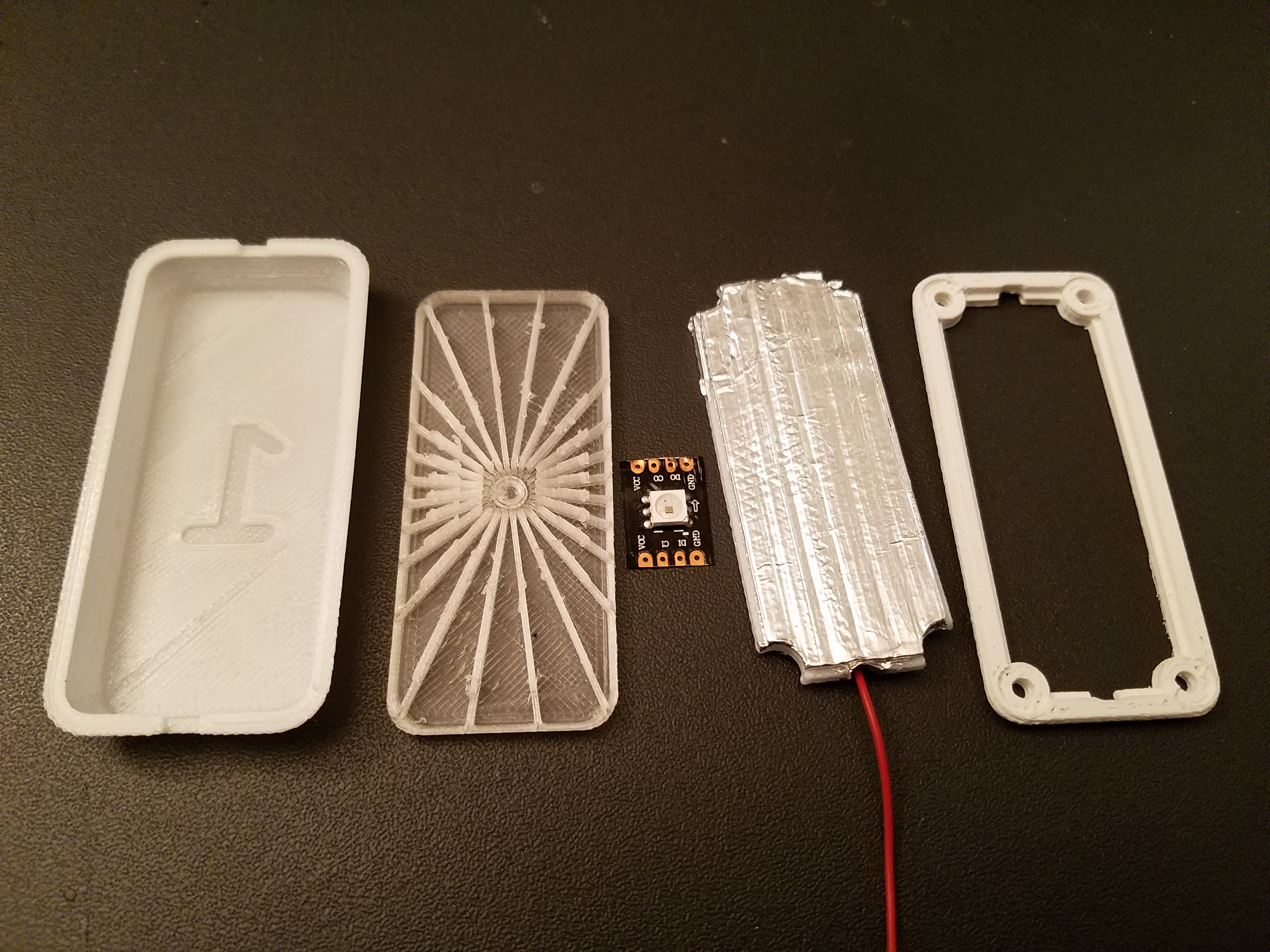
06/26/2017 at 03:01 • 0 commentsMade some minor changes and printed the parts for the button prototype.
![]()
The sensor bit is some aluminum foil spray glued to the TPU pad.
The Bad:
The light pipe is terrible. Nice bright spot and very little actual light piping. I think I need more thickness and an optically accurate cone at the input. The printed approximation instead mimics a fresnel lens and ends up having the opposite effect. I hope I can get away with using PLA, but if not, I have some acrylic waiting in the wings.
The FSR resistance is higher than expected, and not linear. What's worse is it seems to drift with time when held down. I'm going to first try reducing the contact area to increase the force and see what happens.
The Good:
The whole assembly fit together perfectly first try and it stays together.
Printing the TPU cover face down gave a really nice finish and the recessed numbers show through when lit.
-
Blinken Buttons
06/24/2017 at 19:38 • 0 commentsExperimented with making 3D printable buttons.
Tried making a planer design where it could be printed flat, then the buttons popped through to become raised. Might have worked, but then it got a bit more complicated when I decided I wanted some blinken-lights.
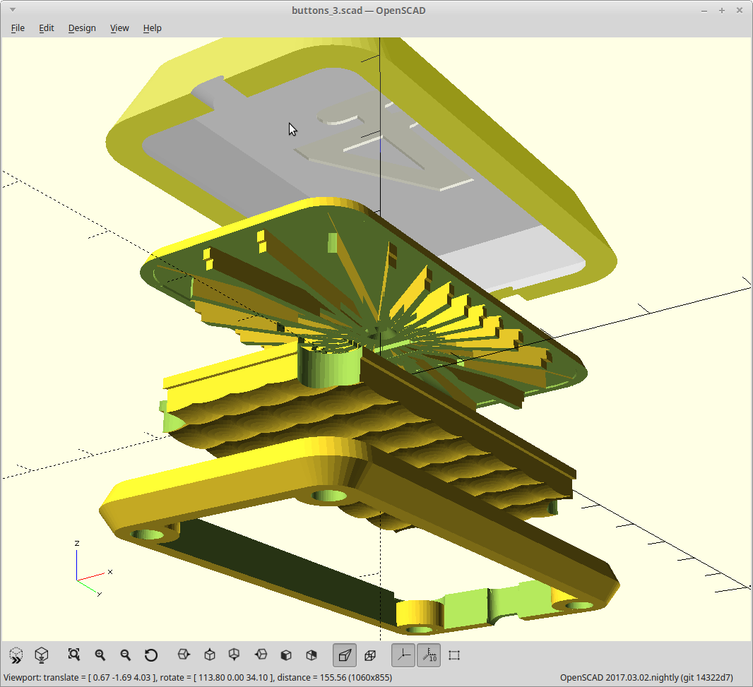
I've settled on a layered approach so everything can be printed in the best material for the job, and without overhangs/supports.
TPU cover, clear PLA light pipe, TPU contact pad, and ABS retainer ring.
![]()
-
Minimalist experimentation.
06/21/2017 at 17:27 • 0 commentsThis could be a really, really simple project with no external components beyond my FSRs.
To do that, I'd need to eliminate the bank of pull-up/pull-down resistors needed to get a voltage for the ADC from my resistors.
Let the experimenting begin.
I read many places that using INPUT_PULLUP and INPUT_PULLDOWN on the ADC was a bad idea. So I started my experiments in the realm of touch sensors.
Touch sensors work by applying a voltage to a pin, then switching to input mode and timing the decay of the voltage. This happens thousands of times a second. A capacitive load will change the decay time and you can detect this change.
I tried something similar, but using the internal capacitance of the Teensy against my FSR for a simple RC circuit.
I discharged a pin using digitalWrite(pin,LOW), switched pinmode to INPUT, then after a short delay do an analogRead(). The pin is pulled high via the FSR. So the lower the FSR resistance, the faster the RC circuit would be pulled high, and the higher the voltage when I did my analogRead(). Sounds good in theory.
It worked, but the readings were pretty bouncy due to my high FSR impedance, and was sensitive to touch as well. Of course it would be... Duh..
The short explanation of why it was so bouncy, is the Teensy is just too fast. It has enough spare cycles that it does oversampling and averaging on the ADC inputs by default. This also means the small internal capacitance of the ADC is particularly tiny as well. I tried making it do single samples with a little improvement, but it's just too erratic and sensitive to environmental changes to be useful.
Ah well, was a cool idea.
Next up, I ignored the collective intelligence of the internet, and tried using INPUT_PULLUP and INPUT_PULLDOWN on the ADC inputs. It worked... well. Much more stable than the RC circuit was, and I can use the oversampling without issues.
Two issues:
- I'm only using 1/7th of the whole ADC range, as the internal pullup resistors are ~20k and my FSR are 140k.
- It only works on the first 10 analog inputs, A0-A9.
The former I can live with. The latter is explained by the fact A10-A13 are not digital capable input pins, so the internal pullup resistors don't exist. Doh.
I tried removing the resistor-less inputs from my loop, but it seems reading above A9 at all makes the upper inputs unstable. No idea why yet.
More testing needed.
-
The circle of life, MIDI style.
06/21/2017 at 16:29 • 0 commentsThe old ones are wearing out. I used conductive foam for my home-made force sensitive resistors, and it eventually stops being foam, and starts being a block of carbon laced goo. This doesn't work well.
So building some new ones.
Was walking through Microcenter and spotted an inexpensive anti-static work surface. Looks pretty tough and is large enough to make two set of pedals for $15.
It's basically a layer of carbon laced rubber and a layer of plain rubber bonded together.
I grabbed a Teensy 3.2 (as it does USB MIDI out of the box), and headed home.
Soldered a few bare copper wires to some perf board and tested the resistance. Two wires, 0.1in apart, 2 in long at 30lbs of force gave ~140k of resistance. That's a bit high for an ADC input to a microcontroller.
Added more wires and it drops some. So the contact area is related to the resistance, although the force per unit area also drops so it's not linear.
Tied both wires together, and measured the resistance to the grounding strap connection. Virtually the same reading.
Moved the contact point around the pad. The resistance varies, but only by 10% across the pad. I can calibrate for that! One connection to each button, and a couple tied grounds and I'm in business.
A project is born.
SMidi - Soft MIDI Pedals
Full function, class compliant MIDI pedals you can roll up.
 Daren Schwenke
