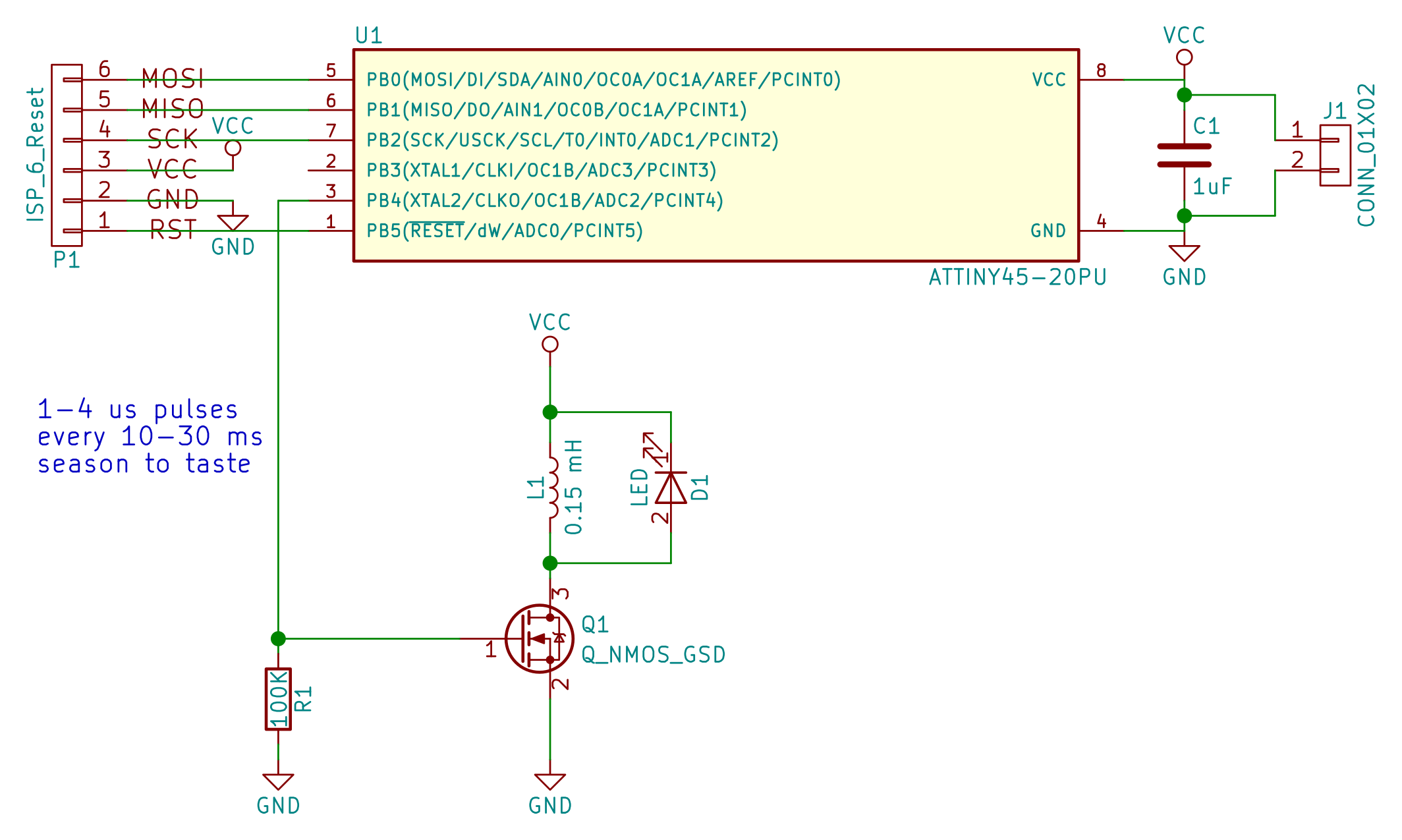
The only interesting part of the project is the FET, inductor, and LED. The rest is just making pulses while using as little power as possible. This is not much of a circuit. Values are what I used, but are probably only really good as a starting point.
Capacitor on the power rail is very necessary. When you crowbar the power rail through the inductor, it makes a predictable sag. I ran it for a while without, and the chip reset with every pulse. Doh!
Also necessary is the pulldown on the FET. If it opens for more than a few microseconds, the inductor acts as a short to ground and it gets very hot. In your hand. As you're trying to program the darn thing.
Anyone wanna bet on how much more/less power a CMOS oscillator and pulse-shaper would use than the AVR?
 Elliot Williams
Discussions
Become a Hackaday.io Member
Create an account to leave a comment. Already have an account? Log In.
I looked into nano-power timer/watchdog ICs as a possibility, but couldn't seem to do better (on paper, anyway) than the PIC12LF1571. I did some experiments on a TritiLED - with the code running at a 16ms timeout, but the LED pulse line commented out, the PIC consumes 2.9 uA. Pulsing the LED once per timeout increases the current to 8.1 uA, two pulses is 14.1 uA, three gives 20.0 uA, four 25.8 uA, and five 31.5 uA. So, there drain is about (3 + 6N) uA for N pulses.
For a single pulse, it's a significant overhead, but as you add more pulses, the PIC part is a smaller percentage. This puts an upper bound on the efficency (assuming no loss in the inductor, etc).
The pulldown is a good idea. I ended up putting a 100-ohm resistor in the supply line for the same sort of protection - that additionally works if the uC goes nuts (cosmic ray or bad programmer) and holds the gate high. It could happen.
Interestingly, a 100-ohm resistor in the supply only reduces the efficiency by a tiny bit. If you are consuming 10uA, the drop across the resistor is only 1mV, so you only waste 0.001/3 = 0.33% of the power in the resistor. In the case of a stuck MOSFET, the 100 ohm resistor limits the current to 30 mA: this will drain the cell very quickly, but only represents 90 mW of power dissipation, which shouldn't cause any thermal issues (use a 1/4 W resistor). This assumes that you have a large enough bypass capacitor after the resistor to supply the pulse current - you don't want to draw the pulse through an extra 100 ohms :-)
My suspicion is that a larger capacitor would help with battery life, too. I use 10uF - I think I read that coin cells are better at continuous low-current than higher pulsed current of even the same average power. The 10uF also helps with measuring the current drain. Pulses confuse my DMM.
Are you sure? yes | no