Built a couple more of these over the weekend, and even whipped up a quick and dirty PCB. I'm thinking of pouring something permanent and waterproof around them, like clear epoxy resin for fiberglass or something, and we'll see if they get the two year's runtime.
I still hadn't really answered the question of how long a pulse is too long, other than by "feel". So I added a resistor (1,775 ohms -- it was in the box) between the light's ground and "real" ground and scoped out the current flowing through the circuit.

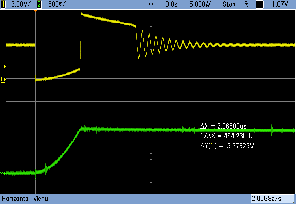
Running for 8 us, you can see the inductor "charging up" in the green trace, and you can also see the power line starting to sag as the "ground" gets pulled up during the transistor's on time in the top graph.
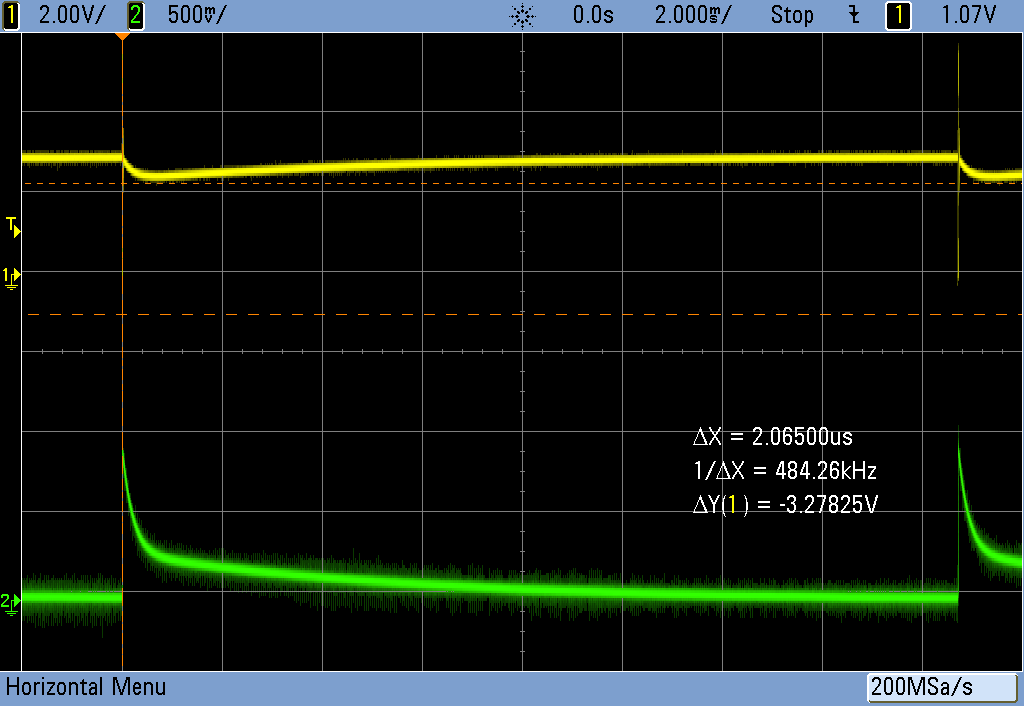
On a cycle-length timescale, changing the yellow trace to the 3.3 V input supply, you can see it getting pulled down and slowly recovering over time. In current (green), the quick peak is the inductor loading up, and the rest is the on-board decoupling capacitor re-charging.

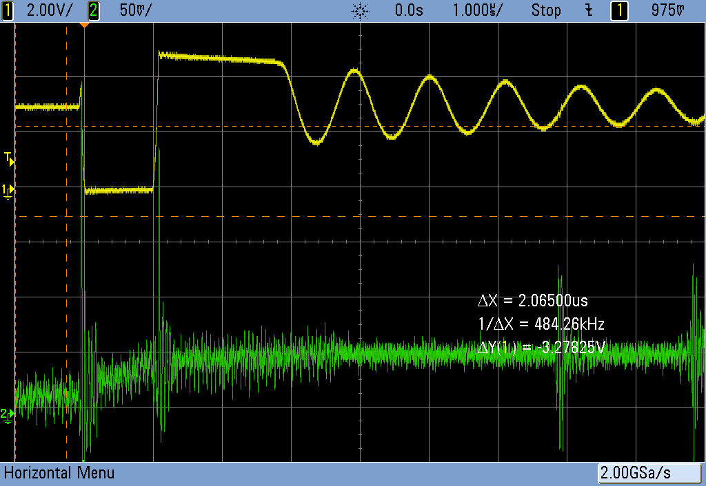
Meanwhile, with 1 us pulses, everything is basically well-behaved again. The current just begins to ramp up before it gets turned back off, storing a relatively small amount of energy, but also not pulling down hard on the voltage rails -- evidence is the flat bottom to the LED voltage (yellow) curve.

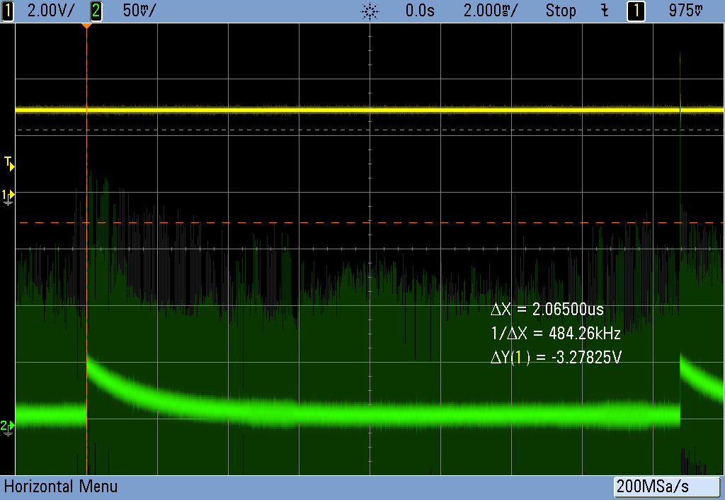
On this scale, the CPU's spikey power demands are visible, and you can also see that it's nowhere near the "fully loaded" zone. That's where I'm running it, and that's about 10 uA total average current draw.
On the cycle time scale, you can see that the voltage rail (here in yellow) doesn't really sag all that much, and that the buffer/decoupling cap on the board charges back up to nominal fairly quickly, leaving only the small, constant draw from the microcontroller.

The conclusion? With these inductors (labelled 0.1 mH) something in the 1-3 microsecond range looks about "right" and drives nearly any LED dimly, with a current consumption of 10-15 uA. I guess I knew this before, but it's reassuring to see measurement match intuition.
Think of the inductor in this circuit as a time-dependent resistor. When you pulse on, it has maximum "resistance", and this decreases as it charges up its mag field. So if you use a larger inductor, you can store more energy while still staying in the high-resistance part of the curve, but you'll have to leave the pulse on longer. Or vice-versa: if you want to pass more energy, and don't want to draw excessive current pulses, you'll want a larger inductor.
Anyway, now I'm probably actually done with this circuit. 10 uA is sufficiently low that it'll run for years on a coin cell, and bright or dim enough with the choice of the right LED. The AVR will run up to 6 V, and doesn't seem to crap out until around 1.2-1.4 V, so power is not a problem. Energy-harvesting, anyone?
If you mess around with the code and find a modulation mode that you like, let me know in the comments?
I'll post up my (KiCad) PCB files in a GitHub just for completeness, although there's not that much to these things.
Enjoy!
 Elliot Williams
Discussions
Become a Hackaday.io Member
Create an account to leave a comment. Already have an account? Log In.