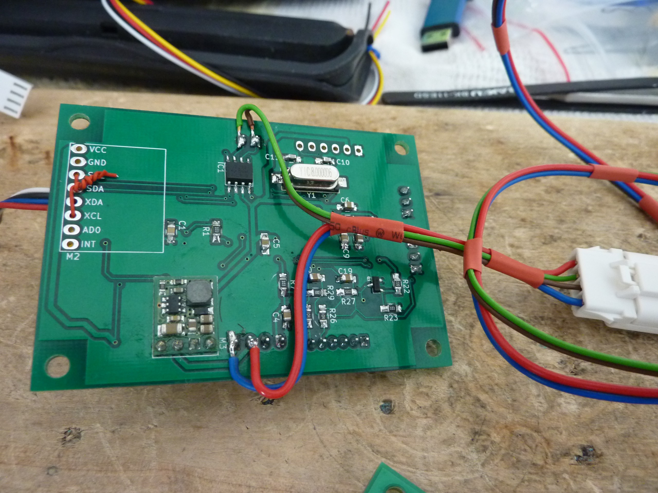
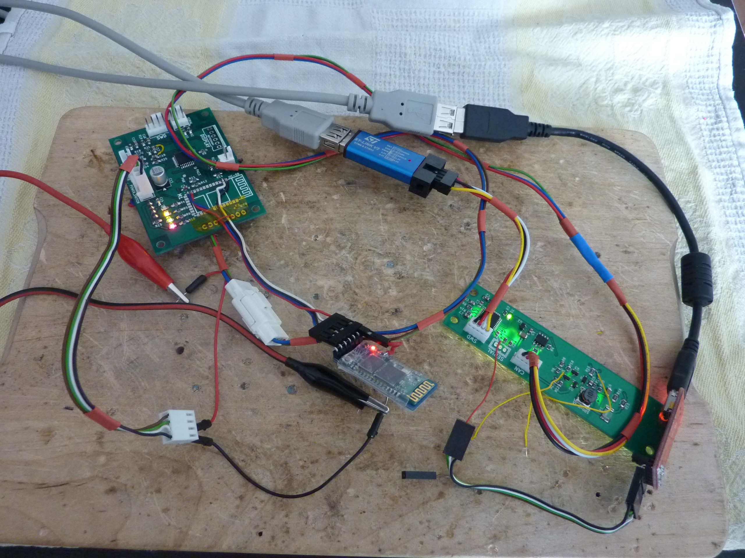
Today I prepared the wiring for FL module. The cable consists of 4 lines: 2 for power (+24V) and 2 for CAN.
The cable from FL is routed to case in the middle of the board. When I was designing Control Unit I didn't anticipate that I'll have to provide power and CAN lines for another board. So now I had to come up with a way how to 'steal' power and CAN from CU board. Fortunately the connectors are through-hole, so I ended up with a pretty elegant solution.
I added MOLEX ditto connector (close to CU), so that I can disconnect CU and FL boards when needed.
Now wiring is complete and I can move on to firmware modifications, so that I can control front lights mode and brightness via Android app.
 Luke
Luke

Discussions
Become a Hackaday.io Member
Create an account to leave a comment. Already have an account? Log In.